
MEMS assembly

A shell and component technology, applied in the field of MEMS modules, can solve problems such as affecting the output signal and reducing the signal-to-noise ratio.

Active Publication Date: 2019-09-10
INFINEON TECH AG
View PDF4 Cites 0 Cited by
  • Summary
  • Abstract
  • Description
  • Claims
  • Application Information

AI Technical Summary

Problems solved by technology

This temperature fluctuation may couple into the housing of the MEMS component and may affect the output signal provided by the MEMS component
As a result, the resulting signal-to-noise ratio (SNR) may be reduced

Method used


Image

  • MEMS assembly
  • MEMS assembly
  • MEMS assembly

Examples


Embodiment Construction

[0013] Before explaining the following embodiments in more detail with reference to the drawings, it is pointed out that identical, functionally identical or equivalent elements, objects, functional blocks and / or method steps in the various figures bear the same reference numerals, Descriptions of these elements, objects, functional blocks and / or method steps shown in different embodiments are thus interchangeable or applicable to each other.

[0014] Various embodiments will now be described in more detail with reference to the accompanying drawings, in which some embodiments are shown. In the drawings, the intensity of lines, layers and / or regions may not be drawn to scale for clarity.

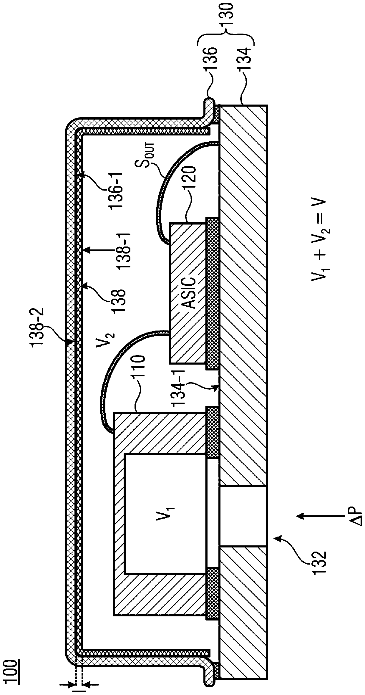
[0015] Refer below figure 1 , in a cross-sectional view, a MEMS module 100 is depicted in schematic diagram form with a MEMS component 110 and an optional circuit arrangement 120 (ASIC: Application Specific Integrated Circuit) electrically coupled to the MEMS component 110 . Such as figur...


PUM


Abstract

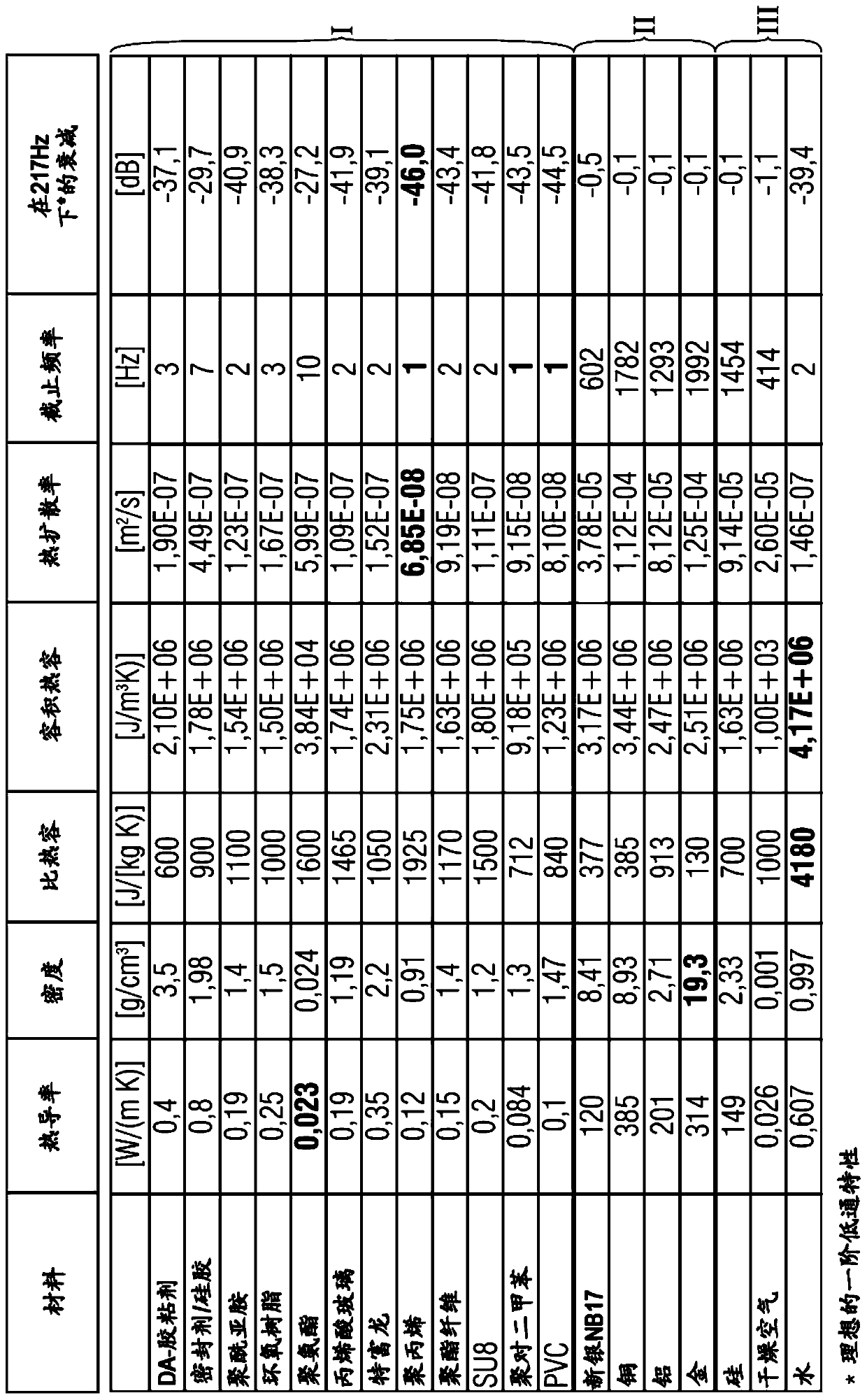
The present invention relates to an MEMS module (100). The MEMS assembly includes a housing having an internal volume (V), wherein the housing (130) has a sound opening to the internal volume (V), a MEMS component in the housing (130) adjacent to the sound opening (132), and a layer element (138) arranged at least regionally at a surface region (134-1, 136-1) of the housing (130) that faces the internal volume (V), wherein the layer element (138) includes a layer material having a lower thermal conductivity and a higher heat capacity than the housing material of the housing that adjoins the layer element.

Description

technical field [0001] Embodiments relate to a MEMS module or MEMS sensor and a method of manufacturing the same. In particular, embodiments relate to a MEMS module in the form of a MEMS acoustic transducer, such as a MEMS microphone, and having a multilayer housing structure. The housing structure is designed to at least reduce the penetration of thermal changes into the interior volume of the MEMS module due to dynamic temperature or thermal fluctuations in the environment of the MEMS module. According to an embodiment, the housing arrangement of the MEMS module is configured as a thermal low-pass filter arrangement. Background technique [0002] A MEMS module generally comprises electronic components arranged on a substrate, for example a MEMS component (MEMS=Micro Electro Mechanical System), which is surrounded by a housing. The housing is designed to protect the MEMS module from the external environment, such as dust, dirt, moisture, etc. Some housings (encapsulation...

Claims


Application Information

Patent Timeline
Patent Type & Authority Applications(China)
IPC IPC(8): H04R19/04
CPCH04R19/04H04R2201/003B81B7/0064B81B7/0077B81B2201/0257H04R19/005H01L2224/48137H01L2224/48091H01L2224/73265H01L2924/15151H01L2924/16152H01L2924/00014B81B7/0032B81B2207/09B81B7/0058B81B7/0061B81B2203/0127B81B2207/012H04R1/021
Inventor M·菲尔德纳N·德米勒里B·戈勒U·克伦拜恩G·洛宁格G·托索里尼A·韦斯鲍尔
Owner INFINEON TECH AG
Learn More