Eureka AIR delivers breakthrough ideas for toughest innovation challenges, trusted by R&D personnel around the world.

Dialyzer glue injection structure and manner

A dialyzer and glue injection technology, which is applied to devices and coatings that apply liquid to the surface, can solve problems such as the performance impact of glue injection products, the performance of rubber materials, and the entry of dust, so as to improve the defoaming effect and prevent Bubble, easy to adjust effect

Inactive Publication Date: 2019-09-17
WUHAN HUACHENG CHUANGFU MEDICAL TECH
View PDF6 Cites 3 Cited by
  • Summary
  • Abstract
  • Description
  • Claims
  • Application Information

AI Technical Summary

Problems solved by technology

[0003] When the current glue injection structure is in use, it is easy to cause bubbles in the glue, which affects the performance of the glue injection product, and during the transportation of the glue, it is easy to cause dust to enter the glue, resulting in a decrease in the performance of the glue

Method used

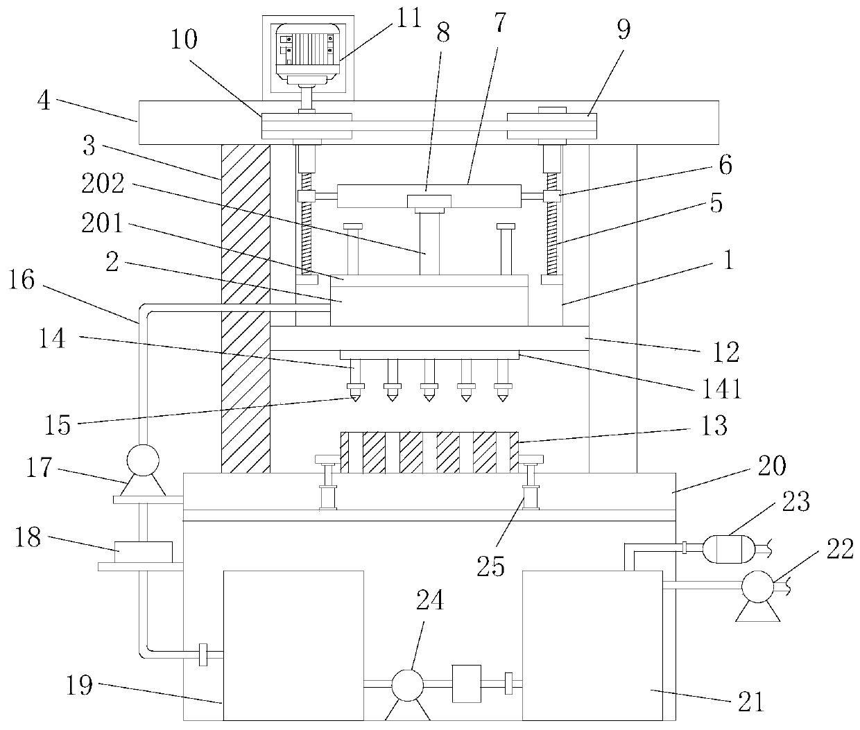

Image

  • Dialyzer glue injection structure and manner
  • Dialyzer glue injection structure and manner
  • Dialyzer glue injection structure and manner

Examples


Embodiment Construction

[0027] The following will clearly and completely describe the technical solutions in the embodiments of the present invention with reference to the accompanying drawings in the embodiments of the present invention. Obviously, the described embodiments are only some, not all, embodiments of the present invention. Based on the embodiments of the present invention, all other embodiments obtained by persons of ordinary skill in the art without making creative efforts belong to the protection scope of the present invention.

[0028] In the description of the present invention, it should be noted that the orientation or positional relationship indicated by the terms "vertical", "upper", "lower", "horizontal" etc. is based on the orientation or positional relationship shown in the drawings, and is only In order to facilitate the description of the present invention and simplify the description, it does not indicate or imply that the device or element referred to must have a specific o...


PUM


Abstract

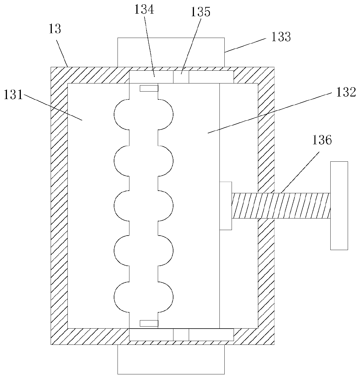
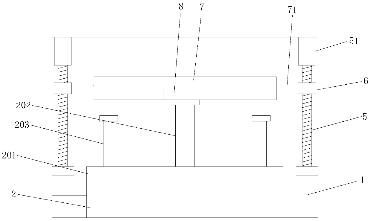
The invention discloses a dialyzer glue injection structure. A glue injection box, a glue injection pipe and a clamp are included. A glue adding barrel is arranged in the glue injection box. A piston plate is arranged in the glue adding barrel. The top center position of the piston plate is fixedly connected with a vertically-arranged piston rod. The two ends of the piston plate are fixedly connected with vertically-arranged connecting rods. A sliding plate is horizontally arranged on the top of the piston rod, a pressure sensor is embedded in the bottom of the sliding plate, and the installing position of the pressure sensor is right opposite to the top of the piston rod. The two ends of the sliding plate are fixedly connected with first connecting plates. One sides of the two first connecting plates are connected to one sides of symmetrically-arranged lead screw nuts. The lead screw nuts are arranged on upper lead screws. The top ends of the lead screws are fixedly connected with connecting columns. One connecting column is rotationally connected with a second belt wheel, and the other connecting column is rotationally connected with a first belt wheel. The glue adding barrel is arranged in the glue injection box, dust is prevented from entering glue, and glue cleanliness is guaranteed.

Description

technical field [0001] The invention relates to the technical field of dialyzer manufacturing devices, in particular to a dialyzer glue injection structure and method. Background technique [0002] Hemodialyzer, referred to as dialyzer for short, is a pipe and container for solute exchange between blood and dialysate, and is a key part of hemodialysis. The dialyzer is mainly composed of a support structure and a dialysis membrane. The latter is an important part of it. It is a semi-permeable membrane that only allows molecules smaller than the membrane aperture to pass through. The membrane materials are improved cellulose membrane and synthetic membrane. Can be made into a high-throughput dialyzer. [0003] When the current glue injection structure is in use, it is easy to cause bubbles in the glue, which affects the performance of the glue injection product, and during the transportation of the glue, it is easy to cause dust to enter the glue, resulting in a decrease in t...

Claims


Application Information

Patent Timeline
IPC IPC(8): B05C5/02B05C11/10B05C13/02
CPCB05C5/0208B05C11/10B05C13/02
Inventor 艾国迎
Owner WUHAN HUACHENG CHUANGFU MEDICAL TECH
Why Eureka
Eureka Blog
Learn More