Supercharge Your Innovation With Domain-Expert AI Agents!

Three-time tempering furnace

A tempering furnace and furnace cover technology, applied in the direction of furnace, quenching agent, furnace type, etc., can solve the problems of reducing heat treatment efficiency, insufficient tempering, increasing cooling time, etc., to save energy and raw material consumption, save The operation of cleaning oil stains and the effect of reducing the cooling time

Pending Publication Date: 2019-09-17
本溪工具股份有限公司
View PDF0 Cites 0 Cited by
  • Summary
  • Abstract
  • Description
  • Claims
  • Application Information

AI Technical Summary

Problems solved by technology

[0002] Tempering is a heat treatment process in which the workpiece is heated to a temperature below Ac1 (the starting temperature of the transformation from pearlite to austenite during heating) after quenching, kept for a certain period of time, and then cooled to room temperature. The existing ordinary online tempering furnace generally At about 10 to 15 meters, due to the short length of the tempering furnace and insufficient tempering during heat treatment production, the hardness of the bimetallic band saw blade product is unstable, which affects the stability of product quality. At the same time, air cooling or oil cooling is generally used for cooling , Cooling by room temperature air will cause the cooling speed to be too slow, or the cooling temperature will not be reached, and the cooling time will be greatly increased, and the efficiency of heat treatment will be reduced. When the saw blade is cooled by oil cooling, the cooling oil will drip It falls to various places inside the main body, which saves the time-consuming and laborious operation of cleaning up the oil stains. At the same time, the oil attached to the surface of the saw blade will affect the effect of the next tempering

Method used


Image

  • Three-time tempering furnace
  • Three-time tempering furnace
  • Three-time tempering furnace

Examples


Embodiment Construction

[0020] The following will clearly and completely describe the technical solutions in the embodiments of the present invention with reference to the accompanying drawings in the embodiments of the present invention. Obviously, the described embodiments are only some, not all, embodiments of the present invention. Based on the embodiments of the present invention, all other embodiments obtained by persons of ordinary skill in the art without making creative efforts belong to the protection scope of the present invention.

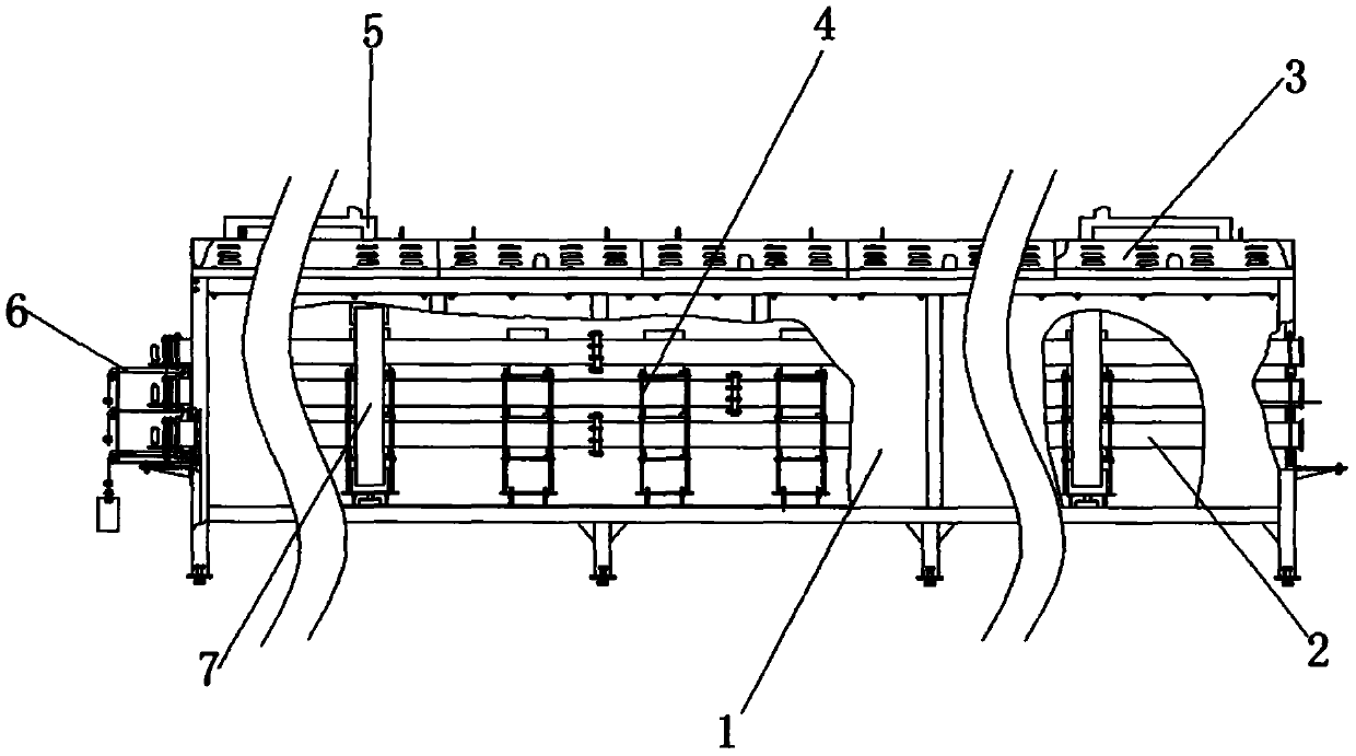
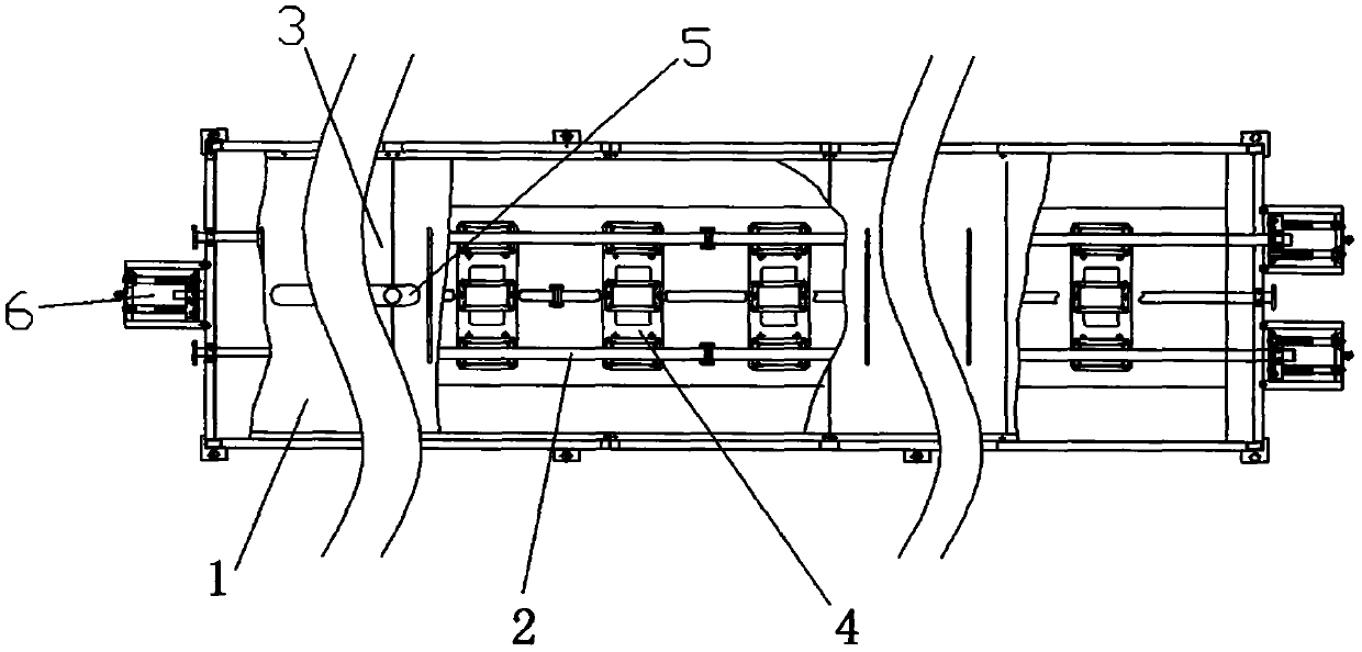
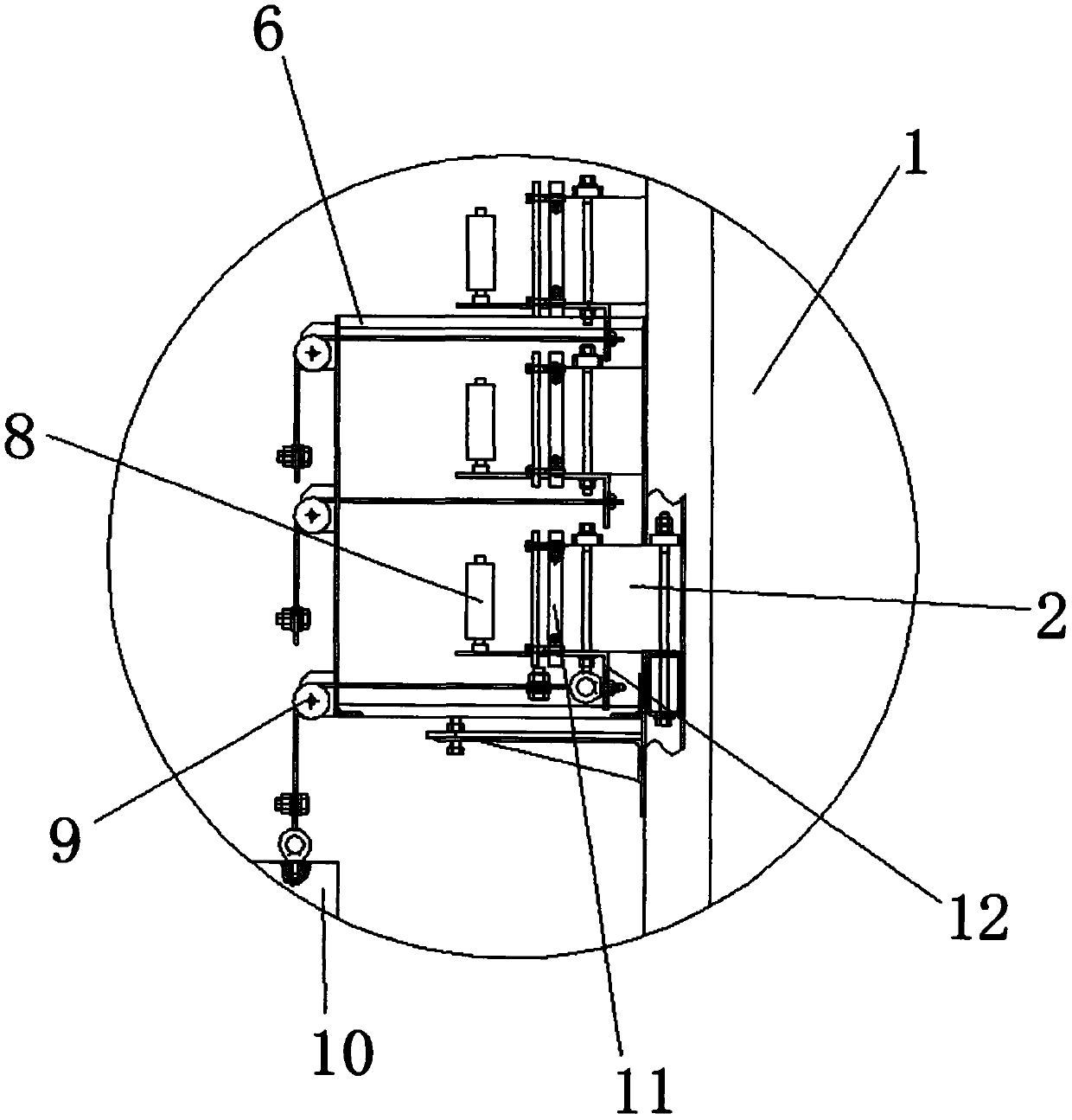
[0021] see Figure 1-8 , the present invention provides a technical solution: a three-time tempering furnace, including a main body 1, a furnace cover 3 is fixedly connected to the top of the main body 1, nine sliding tubes 2 are evenly distributed in three layers of the inner part of the main body 1, and the sliding tubes 2 The bracket 4 is fixedly connected with the main body 1. The bracket 4 evenly distributes the nine sliding tubes 2 inside the main body 1...


PUM


Abstract

The invention discloses a three-time tempering furnace. The three-time tempering furnace comprises a main body, wherein a furnace cover is fixedly connected above the main body, nine sliding pipes are evenly distributed on the inner portion of the main body in three layers, and the sliding pipes are fixedly connected with the main body through a support frame; a ceramic guide rail is arranged in each sliding pipe, and clamping grooves are formed in the two sides of each ceramic guide rail and the middle of the lower portion of each ceramic guide rail; a clamping block is clamped in each clamping groove, and the clamping blocks are fixedly connected with the sliding pipes. The three-time tempering furnace is characterized in that a resistance belt installed in an opening in the ceramic guide rail is repeatedly subjected to heat treatment for three times, so that a heat-treated saw blade can be uniformly heated, and meanwhile, the tempering frequency is increased, the tempering is more sufficient, for three times of tempering is the theoretically optimal tempering frequency, thus ensuring the heat treatment effect; in addition, the cooling is carried out through nitrogen, so that the problems that the cooling speed is too low or the desirable cooling temperature can not be achieved due to the fact that the cooling is conducted through the room temperature air are avoided, and meanwhile the cooling time is greatly reduced.

Description

technical field [0001] The invention relates to the technical field of tempering furnaces, in particular to a three-time tempering furnace. Background technique [0002] Tempering is a heat treatment process in which the workpiece is heated to a temperature below Ac1 (the starting temperature of the transformation from pearlite to austenite during heating) after quenching, kept for a certain period of time, and then cooled to room temperature. The existing ordinary online tempering furnace generally At about 10 to 15 meters, due to the short length of the tempering furnace and insufficient tempering during heat treatment production, the hardness of the bimetallic band saw blade product is unstable, which affects the stability of product quality. At the same time, air cooling or oil cooling is generally used for cooling , Cooling by room temperature air will cause the cooling speed to be too slow, or the cooling temperature will not be reached, and the cooling time will be gr...

Claims


Application Information

Patent Timeline
Patent Type & Authority Applications(China)
IPC IPC(8): C21D1/18C21D1/613C21D1/667C21D9/24
CPCC21D1/18C21D1/613C21D1/667C21D9/24
Inventor 王秀萍隗素艳张博
Owner 本溪工具股份有限公司
Features
  • R&D
  • Intellectual Property
  • Life Sciences
  • Materials
  • Tech Scout
  • Unparalleled Data Quality
  • Higher Quality Content
  • 60% Fewer Hallucinations
Learn More