A production process of underground cement filling and synergistic resource utilization of waste incineration fly ash

A waste incineration fly ash and production process technology, applied in chemical instruments and methods, solid waste removal, transportation and packaging, etc., can solve the problems of large dust, inability to play a good role in landfill, and easy degradation of finished products , to achieve full reaction, convenient batch transportation and landfill, and improved mechanical properties

Active Publication Date: 2022-04-12
NORTH CHINA UNIVERSITY OF SCIENCE AND TECHNOLOGY
View PDF6 Cites 0 Cited by
  • Summary
  • Abstract
  • Description
  • Claims
  • Application Information

AI Technical Summary

Problems solved by technology

[0004] The purpose of the present invention is to solve the problem that the dust is relatively large during operation, and the finished product is easy to degrade after l

Method used


Image

  • A production process of underground cement filling and synergistic resource utilization of waste incineration fly ash
  • A production process of underground cement filling and synergistic resource utilization of waste incineration fly ash
  • A production process of underground cement filling and synergistic resource utilization of waste incineration fly ash

Examples


Example Embodiment

[0025] Example 1:

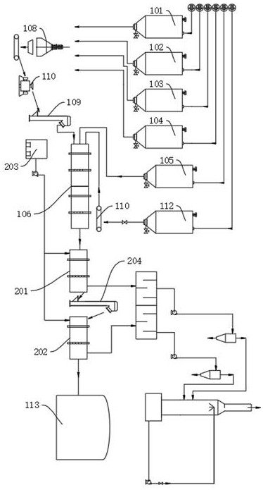
[0026] A production process for underground cement filling and collaborative resource utilization of waste incineration fly ash, comprising: steel slag micropowder storage tank 101, slag powder storage tank 102, desulfurization gypsum storage tank 103, waste incineration fly ash storage tank 104, iron tailing sand storage tank 105 and circulating water tank 112, further comprising: forming machine 106, steel slag micropowder storage tank 101, desulfurization gypsum storage tank 103, waste incineration fly ash storage tank 104 and slag powder storage tank 102 to convey raw materials to disc mixer 108 through conveying belts, respectively, The disc mixer 108 conveys raw materials to the molding machine 106 through the cementitious material bucket elevator 109, a metering belt 110 is arranged between the disc mixer 108 and the cementitious material bucket elevator 109, and the iron tailings sand storage tank 105 is directed to the molding machine 106. The raw ...

Example Embodiment

[0037] Embodiment 2: What is different based on Embodiment 1 is;

[0038] S1, the steel slag micropowder, slag micropowder, desulfurization gypsum and incineration fly ash are 15:4:16:65 according to the mass ratio, transported to the disc mixer 108 for stirring, the stirring temperature is room temperature, the stirring speed is 550N / min, and the stirring The time is 0.6-1.3h;

[0039] S2, adding the material stirred in S1 and the iron tailings sand successively into the molding machine 106 according to the ratio of 1:4, and input raw material water according to 135% of the mass ratio of the materials input into the molding machine 106;

[0040] S3, conveying the output material in the molding machine 106 of S2 to the multi-stage drying mechanism, and sequentially passing through the primary drying machine 201 and the secondary drying machine 202 to control the moisture content of the output material in the multi-level drying mechanism to be 30%;

[0041] S4. The finished pr...


PUM

PropertyMeasurementUnit
Specific surface areaaaaaaaaaaa

Abstract

The invention discloses a production process of underground cement filling and synergistic resource utilization of waste incineration fly ash, which belongs to the field of fly ash solidification. A production process for underground cement filling and synergistic resource utilization of waste incineration fly ash. The invention makes the cementitious material first, and then adds iron tailing sand, so that the fly ash can be fully dissolved in the cement, so that the overall structure is more compact, The reaction of fly ash is absolutely sufficient, the qualification rate of heavy metals is greatly improved, and the technical problem of incomplete direct pulping reaction is solved. The moisture content of fly ash reaches the specified standard, which is convenient for bulk transportation and landfill. Due to the use of prefabrication and drying and dehydration treatment processes, there will be no basis for dust generation at the site, and the dirty, messy and poor phenomenon of the existing fly ash treatment workshop will be completely changed, and the health of workers will be protected to the greatest extent.

Description

technical field [0001] The invention relates to the field of fly ash solidification, in particular to an underground cemented filling collaborative resource utilization waste incineration fly ash production process. Background technique [0002] In the prior art, the most economical and common process for heavy metal treatment in power generation fly ash is the chelation solidification method. The principle is to add 1-3% heavy metal chelating agent and 20-30% water to the fly ash, stir briefly, let the chelating agent react with the heavy metal ions in the fly ash to form a chelate, and finally add cement to solidify. Heavy metals and moisture content (<30%) are tested and passed into domestic landfills. However, in the existing fly ash solidification process, due to the limitation of the proportion of water and ash, and the nonpolar performance of fly ash, the contact and stirring between the chelating agent and the fly ash are not sufficient, and a large part of the h...

Claims


Application Information

Patent Timeline
IPC IPC(8): B09B3/38B09B3/40B09B5/00B09B101/30
CPCB09B3/00B09B5/00B09B2101/30
Inventor 梁银英张晋霞牛福生王晓红冯洪均董佳静
Owner NORTH CHINA UNIVERSITY OF SCIENCE AND TECHNOLOGY
Why Eureka
Try Eureka