Building material processing device

A technology for processing equipment and building materials, which is applied in the direction of unloading equipment, clay preparation equipment, cement mixing equipment, etc., can solve the problems of low concrete mixing efficiency, concrete cannot be discharged quickly, etc., to reduce ineffective mixing time and reduce mixing costs , the effect of fast mixing speed

Active Publication Date: 2019-09-27
CHONGQING VOCATIONAL INST OF ENG
View PDF6 Cites 6 Cited by
  • Summary
  • Abstract
  • Description
  • Claims
  • Application Information

AI Technical Summary

Problems solved by technology

[0004] In order to solve the above problems, the present invention provides a building material processing device, which solves the problems of low efficiency of concrete mixing and that the concrete cannot be quickly discharged from the mixing drum

Method used


Image

  • Building material processing device
  • Building material processing device
  • Building material processing device

Examples


Embodiment 1

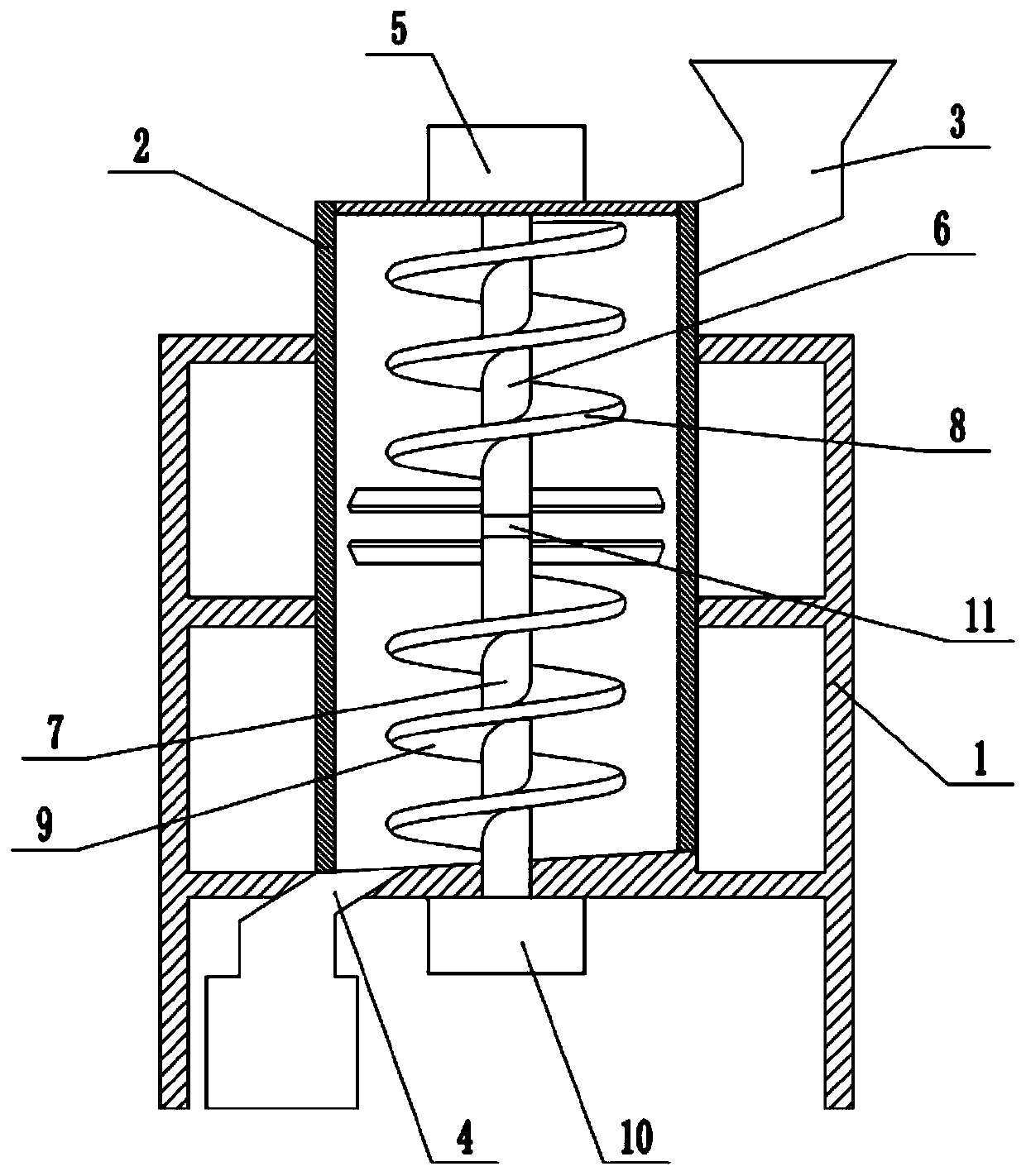
[0037] Embodiment one is basically as figure 1 and figure 2 As shown, a building material processing device includes a support frame 1, a vertically arranged mixing drum 2 is fixedly connected to the supporting frame 1, the upper right side of the mixing drum 2 is provided with a feed port 3, and the bottom of the mixing drum 2 is provided There is a discharge port 4, a rotating shaft is coaxial with the mixing drum 2 in the mixing drum 2, and the top of the mixing drum 2 is fixedly connected with a drive unit that drives the rotating shaft to rotate through bolts. In this embodiment, the driving unit includes an output shaft that is set downward. The first motor 5, the top of the rotating shaft is fixedly connected with the output shaft of the first motor 5 through a shaft coupling.

[0038] like figure 1 As shown, the rotating shaft includes an upper rotating shaft 6 and a lower rotating shaft 7 linked to each other. The lower rotating shaft 7 is close to the discharge po...

Embodiment 2

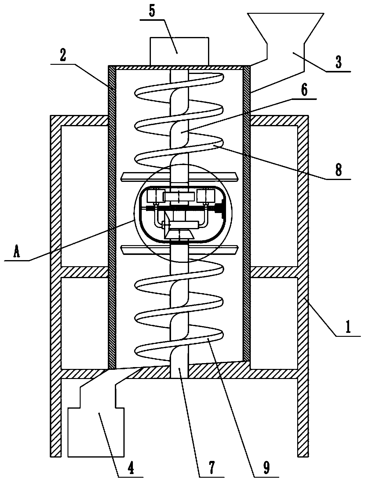
[0049] The difference between the second embodiment and the first embodiment is that the reversing mechanism is improved.

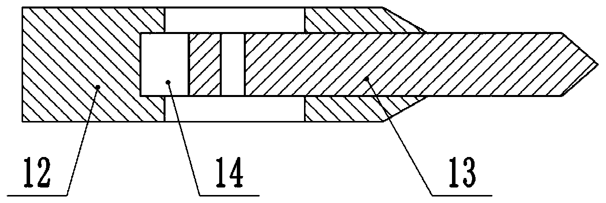
[0050] to combine image 3 and Figure 4 As shown, a reversing mechanism is provided between the upper rotating shaft 6 and the lower rotating shaft 7, and the reversing mechanism includes a driving wheel 15, a first spur gear 16, a second spur gear 17, a first bevel gear 18, a second bevel gear 19, Driven shaft 20 and switcher.

[0051] Switcher comprises fixed plate 21, slide plate 22, electromagnet and protective cover 23, and the outer wall of protective cover 23 is connected smoothly, is all connected by bearing between upper rotating shaft 6 and lower rotating shaft 7 and protective cover 23, and driving wheel 15, the first The spur gear 16 , the second spur gear 17 , the first bevel gear 18 , the second bevel gear 19 , the driven shaft 20 and the switch are all located in the protective cover 23 . like Figure 4 As shown, the driving wheel 15 i...


PUM


Abstract

The invention relates to the technical field of building material equipment, in particular to a building material processing device. The building material processing device comprises a supporting frame; the supporting frame is fixedly connected with a stirring cylinder; a material discharging port is formed at the bottom of the stirring cylinder; a rotating shaft is coaxially arranged in the stirring cylinder; a driving unit for driving the rotating shaft to rotate is arranged on the stirring cylinder; the rotating shaft comprises an upper rotating shaft and a lower rotating shaft which are mutually linked; the upper rotating shaft is fixedly connected with an upper spiral sheet; the lower rotating shaft is fixedly connected with a lower spiral sheet; a reversing mechanism for changing the relative rotation direction of the upper rotating shaft and the lower rotating shaft is arranged between the upper rotating shaft and the lower rotating shaft; and the lower rotating shaft is close to the material discharging port. The rotation direction of the lower spiral sheet is changed sequentially through a switching mechanism, and the upper spiral sheet and the lower spiral sheet cooperate with each other to sequentially complete stirring operation and material discharging operation, so that the problems in the prior art that the stirring efficiency is low and the material discharging speed is low are solved.

Description

technical field [0001] The invention relates to the technical field of building material equipment, in particular to a building material processing device. Background technique [0002] Concrete is a commonly used building material in the field of construction. Concrete refers to the general designation of engineering composite materials that use cementitious materials to cement aggregates into a whole. The term concrete usually refers to the use of cement as cementitious materials, sand, Stone is used as aggregate, mixed with water (may contain admixtures and admixtures) in a certain proportion, and the cement concrete obtained by stirring is widely used in civil engineering. Due to the wide use of concrete, the concrete mixing device also follows developed. [0003] Existing concrete mixing devices generally use a rotating shaft to drive the stirring paddles to rotate, so that the stirring paddles can stir and mix the raw materials of the concrete. For example, the utilit...

Claims


Application Information

Patent Timeline
Patent Type & Authority Applications(China)
IPC IPC(8): B28C5/16B28C7/04B28C7/16
CPCB28C5/16B28C7/04B28C7/162
Inventor 李蓓蕾余齐琴
Owner CHONGQING VOCATIONAL INST OF ENG
Why Eureka
Try Eureka