
Calibration method and control method for permanent magnet synchronous motor, and bench test control system

A technology for permanent magnet synchronous motors and calibration methods, applied in control systems, motor control, high-speed motor control, etc., can solve the problems of low efficiency of permanent magnet synchronous motors, reduce the difficulty of implementation and the amount of changes, and balance copper consumption and efficiency high effect

Active Publication Date: 2019-09-27
ZHENGZHOU YUTONG BUS CO LTD
View PDF8 Cites 9 Cited by
  • Summary
  • Abstract
  • Description
  • Claims
  • Application Information

AI Technical Summary

Problems solved by technology

[0005] The purpose of the present invention is to provide a calibration method, control method and bench test control system for permanent magnet synchronous motors, which are used to solve the problem of low efficiency of permanent magnet synchronous motors

Method used


Image

  • Calibration method and control method for permanent magnet synchronous motor, and bench test control system
  • Calibration method and control method for permanent magnet synchronous motor, and bench test control system
  • Calibration method and control method for permanent magnet synchronous motor, and bench test control system

Examples


Embodiment Construction

[0031] In order to make the object, technical solution and advantages of the present invention clearer, the present invention will be further described in detail below in conjunction with the accompanying drawings and specific embodiments.

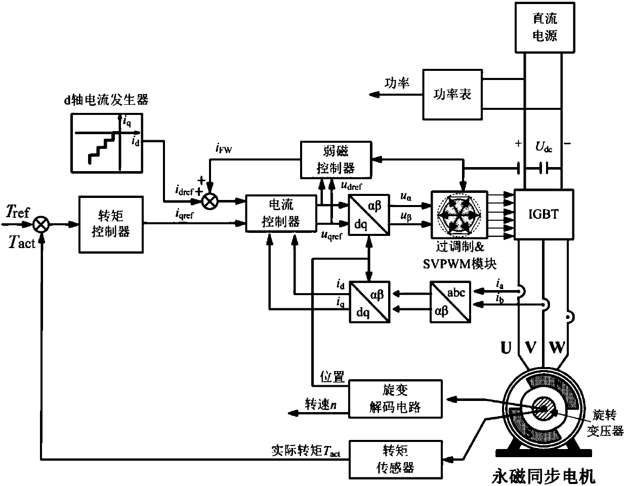
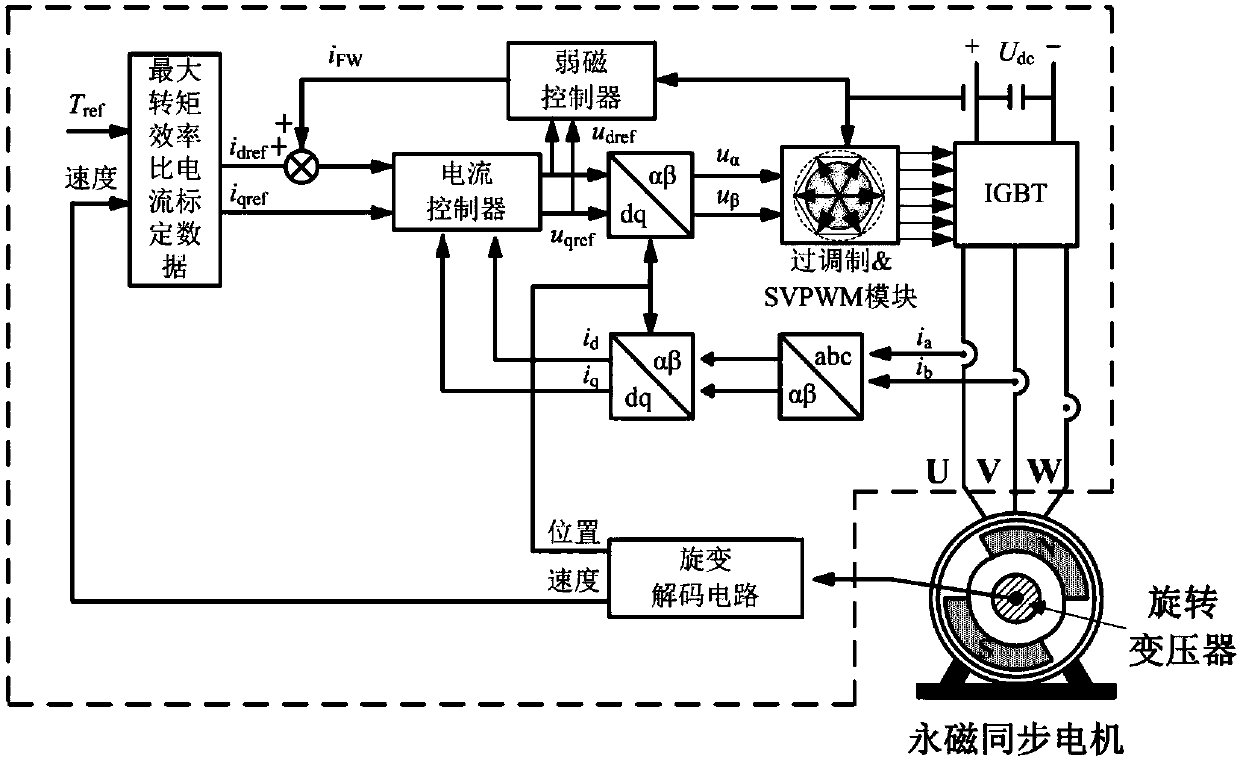
[0032] The invention provides a control method of a permanent magnet synchronous motor. The control method introduces power feedback, distributes the AC and DC axis current components according to the DC input power of the controller in the full range of working conditions, balances iron consumption and copper consumption, and realizes system efficiency. Highest. The control method adopts the motor control algorithm design process commonly used in electric vehicles, that is, the motor is calibrated on the bench first, and then the motor control program is made based on the motor calibration data, which can not only ensure the dynamic response performance of the motor control, but also is common in electric vehicles. The software and hardwa...


PUM


Abstract

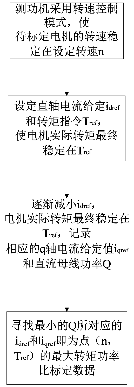
The invention relates to a calibration method and a control method for a permanent magnet synchronous motor, and a bench test control system. The calibration method comprises the steps of: enabling a dynamometer to use a rotational speed control mode in order to stabilize the rotational speed of a motor to be calibrated at a set rotational speed n; enabling the motor to be calibrated to use a torque control mode, setting a d-axis current given value idref1 and a torque instruction value Tref, and after the motor operates stably, recording the corresponding q-axis current given value iqref1 and the DC bus power Q1; giving a d-axis current given value idrefj, 2 <= j <= n, idref1 > idref2 > ...> idrefn, and under each idrefj, recording the corresponding iqrefj and Qj after the motor runs stably; searching for the idrefj and iqrefj, corresponding to the minimum Qj, as the maximum torque power ratio calibration data corresponding to the Tref and n; and repeating the above processes to obtain maximum torque power ratio calibration data corresponding to different torque instruction values and the rotational speeds. The method, by calibrating the maximum torque power ratios corresponding to different torque instruction values and rotational speeds, finally realizes the control of a motor system and achieves the highest system efficiency.

Description

technical field [0001] The invention relates to a calibration method, a control method and a bench test control system of a permanent magnet synchronous motor, belonging to the technical field of permanent magnet synchronous motor control. Background technique [0002] Permanent magnet synchronous motor is the main power executive component of new energy vehicles, and the efficiency of the motor system has an important impact on the energy consumption and driving range of the vehicle. For the existing vehicle permanent magnet synchronous motor control algorithm, the maximum torque current ratio control algorithm (MTPA, Maximum Torque per Ampere) is generally used below the base speed of the motor, and the field weakening algorithm (FW, Field Weakening) is used above the base speed of the motor. ). The maximum torque current ratio control is also called the minimum stator current control, that is, under the condition of given torque, the stator current is minimized by optima...

Claims


Application Information

Patent Timeline
IPC IPC(8): H02P6/28H02P6/34H02P23/00H02P27/08
CPCH02P6/28H02P6/34H02P23/009H02P27/085H02P2205/05H02P2205/07H02P2209/11
Inventor 纪秉男郑维韩光辉张振宁靳超张广利王志中
Owner ZHENGZHOU YUTONG BUS CO LTD
Learn More