Catalytic cracking method and system

A catalytic cracking and lean gas technology, which is applied in the field of catalytic cracking methods and catalytic cracking systems, can solve the problems of increased gas phase load, low absorption efficiency, and high propylene content of the reabsorption tower, so as to reduce energy consumption of the device and reduce dry gas and coke Yield, effect of optimized operating conditions

Active Publication Date: 2019-10-01
CHINA PETROLEUM & CHEM CORP
View PDF6 Cites 0 Cited by
  • Summary
  • Abstract
  • Description
  • Claims
  • Application Information

AI Technical Summary

Problems solved by technology

[0010] The purpose of the present invention is to provide a catalytic cracking method and system in order to overcome the problems existing in the prior art when dry gas is used as the pre-lifting medium, the gas phase load of the reabsorption tower is increased, the absorption efficiency is low, and the content of propylene in the dry gas is high.

Method used


Image

  • Catalytic cracking method and system
  • Catalytic cracking method and system
  • Catalytic cracking method and system

Examples


Embodiment 1

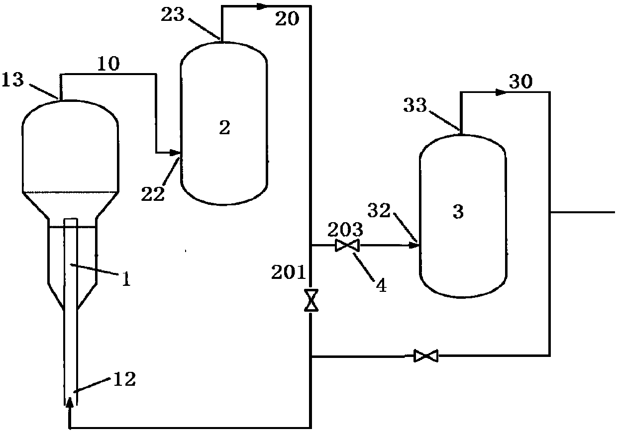
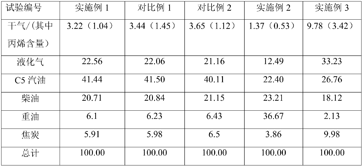
[0058] Feed catalytic cracking raw materials into a riser reactor of equal diameter, react under the conditions of temperature 502°C and pressure 0.2MPa, separate the gas phase product from the reaction product, and lead the gas phase product to the spray absorption tower through pipeline 10 Treatment, the absorbent used is stabilized gasoline. The resulting lean gas composition after absorbent treatment is 96% by volume C 1 、C 2 , about 3.9 vol% C 3 、C 4 and about 0.1% by volume of C 5 the above components. 30% by volume of the lean gas is injected into the riser reactor through the pre-lift medium inlet 12 at the bottom of the riser reactor, and the rest of the lean gas is injected into the reabsorption tower for further processing, wherein the pressure of the lean gas is 1.25 MPa. The obtained product distribution list is shown in Table 2.

Embodiment 2

[0060] Feed catalytic cracking raw materials into a riser reactor of equal diameter, react under the conditions of temperature 430°C and pressure 0.15MPa, separate the gas phase product from the reaction product, and lead the gas phase product to the spray absorption tower through pipeline 10 Treatment, the absorbent used is stabilized gasoline. The resulting lean gas composition after absorbent treatment is 90% by volume C 1 、C 2 , about 9.5 vol% C 3 、C 4 and about 0.5% by volume of C 5 the above components. 50% by volume of the lean gas is injected into the riser reactor through the pre-lift medium inlet 12 at the bottom of the riser reactor, and the rest of the lean gas is injected into the reabsorption tower for further processing, wherein the lean gas pressure is 0.8 MPa. The obtained product distribution list is shown in Table 2.

Embodiment 3

[0062] Feed catalytic cracking raw materials into a riser reactor of equal diameter, react under the conditions of temperature 600°C and pressure 0.3 MPa, separate gas phase products from reaction products, and lead gas phase products to spray absorption tower through pipeline 10 Treatment, the absorbent used is stabilized gasoline. The resulting lean gas composition after absorbent treatment is 99% by volume C 1 、C 2 , about 0.9 vol% C 3 、C 4 and about 0.1% by volume of C 5 the above components. 21% by volume of the lean gas is injected into the riser reactor through the pre-lift medium inlet 12 at the bottom of the riser reactor, and the rest of the lean gas is injected into the reabsorption tower for further processing, wherein the pressure of the lean gas is 1.5 MPa. The obtained product distribution list is shown in Table 2.


PUM


Abstract

The invention relates to the field of catalytic cracking reactions, and discloses a catalytic cracking method and a catalytic cracking system. The method is characterized in that a catalytic crackingraw material is subjected to a catalytic cracking reaction in a riser reactor under the action of a pre-lifting medium; a gas phase is separated from a reaction product; the gas phase is injected intoan absorption tower for treatment; lean gas is collected from the top of the absorption tower, and at least part of the lean gas is used as the pre-lifting medium. The catalytic cracking system comprises a reaction device configured with the riser reactor and the absorption tower; the gas phase outlet on the top of the reaction device is communicated with the gas phase inlet of the absorption tower; the lean gas outlet on the top of the absorption tower is communicated with the pre-lifting medium inlet at the bottom of the riser reactor. Through adopting the catalytic cracking method and thecatalytic cracking system disclosed by the invention, the gas phase load of a reabsorption tower can be reduced; the absorption effect is effectively improved; propylene components carried in dry gasare reduced.

Description

technical field [0001] The invention relates to the field of catalytic cracking reactions, in particular to a catalytic cracking method and a catalytic cracking system. Background technique [0002] The pre-lifting technology at the bottom of the catalytic cracking riser is a process technology commonly used in various catalytic cracking units at present. By setting a pre-lifting section at the bottom of the riser, this technology can prevent the catalyst from back-mixing and depositing at the bottom of the riser and promote the catalyst to flow in the feed nozzle. Uniform distribution and good oil contact. The pre-lift medium currently used is generally steam and dry gas. When steam is used as a lifting medium, it will cause the thermal collapse of the catalyst, generate fine powder, and increase the consumption of the catalyst. The latent heat of vaporization of water is large, and the increase in the amount of water vapor will increase the cooling load of the top cooler...

Claims


Application Information

Patent Timeline
Patent Type & Authority Applications(China)
IPC IPC(8): C10G55/06
CPCC10G55/06
Inventor 黄晓明王强徐成裕鹿志勇孙士勇
Owner CHINA PETROLEUM & CHEM CORP
Why Eureka
Try Eureka