Efficient laser continuous handheld welding equipment

A welding equipment and handheld technology, which is applied in the field of high-efficiency laser continuous handheld welding equipment, can solve the problems of inconvenient handling and movement, low number of laser lasers, and large volume, and achieve the effect of easy control of power, easy adjustment of parameters, and large energy

Inactive Publication Date: 2019-10-08
SHENZHEN LEIKANG MACHINERY EQUIP CO LTD
View PDF4 Cites 4 Cited by
  • Summary
  • Abstract
  • Description
  • Claims
  • Application Information

AI Technical Summary

Problems solved by technology

[0003] The defects of the existing hand-held laser welding equipment are as follows: 1) Since the pulsed laser power source is used, the frequency of the emitted laser is very low, and the energy of a single laser pulse is large, but the number of lasers emitted by the laser per second is low That is, the frequency is low, the maximum is about 60 Hz, and the products that require high sealing of the weld cannot meet the process; 2) The volume is large, it is inconvenient to carry and move, and it is inconvenient to use

Method used


Image

  • Efficient laser continuous handheld welding equipment
  • Efficient laser continuous handheld welding equipment
  • Efficient laser continuous handheld welding equipment

Examples


Embodiment 1

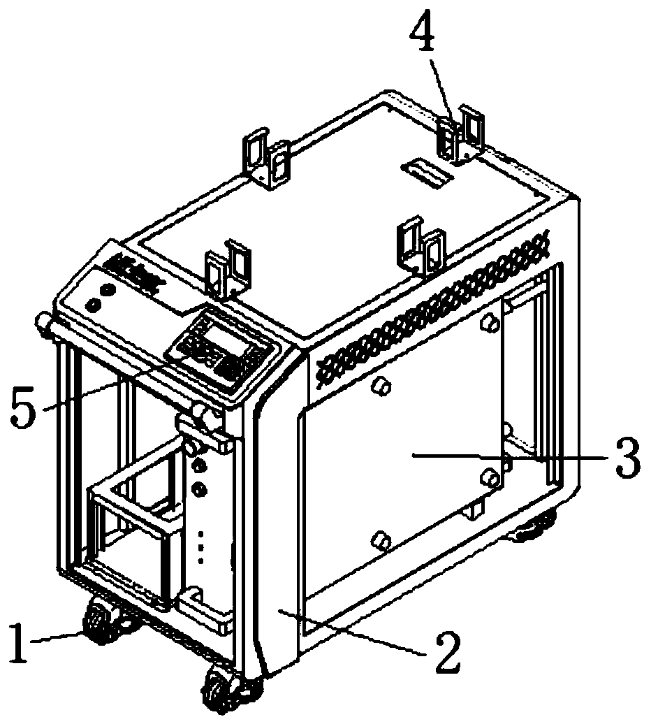
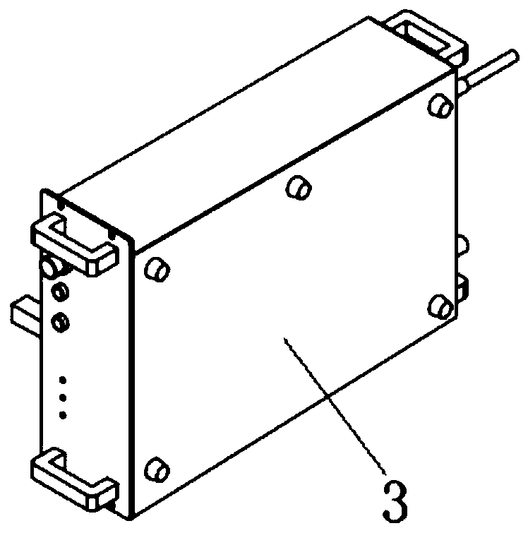
[0029] see Figure 1-4 , in the embodiment of the present invention, a high-efficiency laser continuous handheld welding equipment includes a cabinet 2, a continuous fiber laser 3 is installed inside the cabinet 2, and a circuit control system is installed in the cabinet 2 above the continuous fiber laser 3, The continuous fiber laser 3 is a device that generates high voltage and emits laser light after the circuit is processed. An operation panel 5 is installed on the upper slope of the cabinet 2, and a plurality of optical fiber line placement seats 4 are installed on the top of the cabinet 2. After welding Afterwards, the overlong optical fiber line and laser rod 8 can be placed to prevent damage caused by transportation.

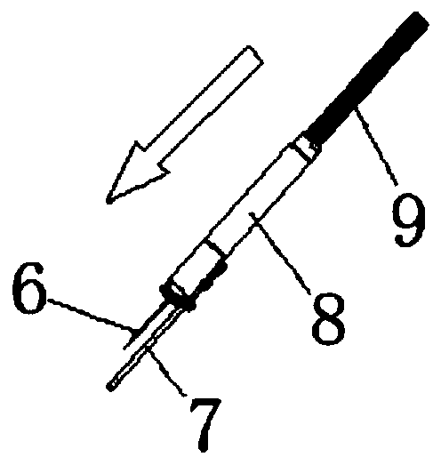
[0030] like figure 2 As shown, it also includes a hand-held laser rod 8 connected to the continuous fiber laser 3, and the connecting wire harness between the laser rod 8 and the continuous fiber laser 3 is provided with a bellows 9 to reduce the wear ...

Embodiment 2

[0032] see figure 1 and 4 , the difference between this embodiment and embodiment 1 is:

[0033] Further, a plurality of casters 1 are installed on the bottom of the cabinet 2 to facilitate the movement and fixation of the device.

[0034] Further, the inner side of the cabinet 2 is also installed with a water cooling device for cooling the continuous fiber laser 3, and the water cooling device is used to cool the temperature generated by the laser to the components to prolong the service life.

[0035] Further, the model of the operation panel 5 is XP3-18T, and the operation panel 5 is designed with a button screen. The operation panel 5 is provided with a power switch, a shutter switch and a man-machine interface, and a laser can be set on the button screen. Parameters, by adjusting the laser parameters to achieve the desired laser process.

[0036] Further, there are at least four optical fiber wire placing seats 4 on the top of the cabinet 2 , and the laser rod 8 can be...


PUM

PropertyMeasurementUnit
diameteraaaaaaaaaa

Abstract

The invention relates to welding equipment, in particular to efficient laser continuous handheld welding equipment. The equipment comprises a cabinet; a continuous optical fiber laser is mounted on the inner side of the cabinet; an operation panel is mounted on the inclined surface of the upper part of the cabinet; and multiple optical cable placing bases are mounted at the top of the cabinet. Theefficient laser continuous handheld welding equipment further comprises a handheld laser rod connected with the continuous optical fiber laser. The efficient laser continuous handheld welding equipment adopts the continuous optical fiber laser, has the characteristics of small size, high energy, easy parameter adjustment and the like, realizes basic laser parameter control, and is suitable for more laser machining places with higher laser heat requirements; and the handheld laser rod can resist high-power laser radiation, is more portable, is controlled without wasting power, and is easier tomaster the strength.

Description

technical field [0001] The invention relates to a welding device, in particular to a high-efficiency laser continuous hand-held welding device. Background technique [0002] Laser welding is suitable for various advertising, lighting and mold industries, such as photoelectric communication devices, medical treatment, electronics, copper parts, aluminum parts and small welding processing industries. The working mode of the laser hand-held welding machine is as follows: use YAG pulse laser power supply to provide power, emit low-frequency pulse laser, single pulse energy is strong, hand-held welding is flexible and changeable, and the welding distance can be longer. Use a hand-held welding torch to replace the previous fixed optical path. The hand-held fiber laser welding machine is mainly for long-distance, laser welding of large workpieces. The heat effect during welding is small, and it will not cause deformation, blackening, and traces on the back of the workpiece, and Th...

Claims


Application Information

Patent Timeline
Patent Type & Authority Applications(China)
IPC IPC(8): B23K26/21B23K26/0622B23K26/70
CPCB23K26/0622B23K26/21B23K26/702
Inventor 唐军刘勇武
Owner SHENZHEN LEIKANG MACHINERY EQUIP CO LTD
Why Eureka
Try Eureka