Atomic layer deposition system

An atomic layer deposition and fluid technology, which is applied in coatings, metal material coating processes, gaseous chemical plating, etc., can solve the problem of inability to control the flow of the surface deposition process and the process of emptying the reaction by-products separately, and it is difficult to achieve rapid reaction by-products Exhaust gas flow, etc.

Active Publication Date: 2019-10-11
SHAANXI COAL & CHEM TECH INST +1
View PDF2 Cites 1 Cited by
  • Summary
  • Abstract
  • Description
  • Claims
  • Application Information

AI Technical Summary

Problems solved by technology

Although this flow can ensure the best aerodynamic environment for film growth, it is difficult to achieve the gas flow required for the rapid discharge of reaction by-products
The traditional atomic layer deposition system only sets a unified gas flow rate, and cannot implement separate flow control for the surface deposition process and the reaction by-product emptying process

Method used


Image

  • Atomic layer deposition system

Examples


Embodiment 1

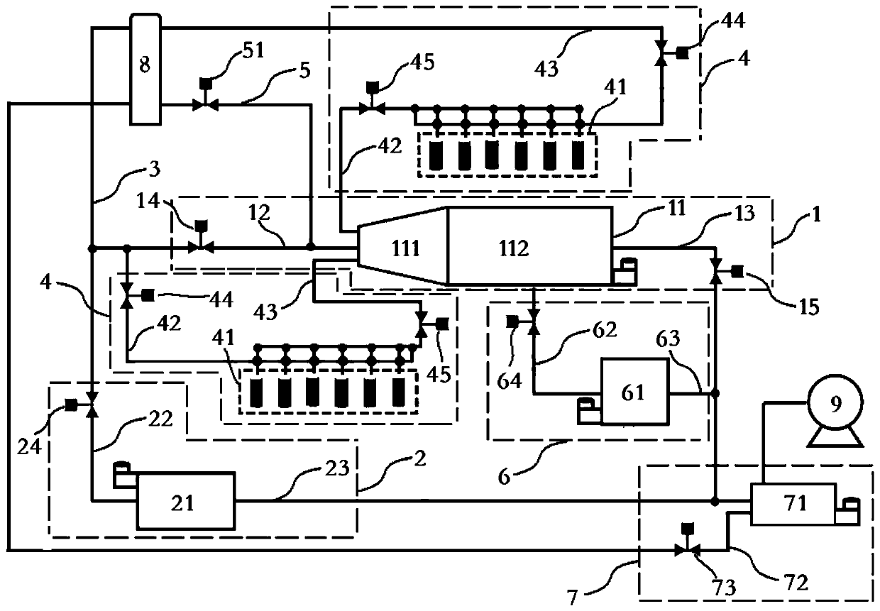
[0060] Al by atomic layer deposition 2 o 3 For example, the precursor reactants are TMA and H 2 O. TMA and H 2 The O sources are respectively installed in two different reaction source arrays (see figure 1 Two different reactant source arrays 41) in order to avoid their possible in-line mixing. The average temperature in the reaction chamber is 150°C, the sample heating temperature is 250°C, and the gas pipeline temperature is 50°C. The time sequence of reactant injection and by-product evacuation for single-layer coating is: 100 milliseconds H 2 O molecule injection + 500 millisecond reaction by-product discharge + 100 millisecond TMA molecule injection + 300 millisecond reaction by-product discharge. The system uses a BOC Edwards mechanical vacuum pump to establish a vacuum environment in the reaction chamber. Flow control adopts MKS company IP66 series mass flow controller (MFC). The gas valve adopts Swagelok company DL series atomic layer deposition special valve, ...

Embodiment 2

[0067] Atomic Layer Deposition of TiO 2 As an example, the precursor reaction sources are respectively TiCl 4 with H 2 O. TiCl 4 with H 2 The O sources are respectively installed in two different reaction source arrays (see figure 1 Two different reactant source arrays 41) in order to avoid their possible in-line mixing. The average temperature in the reaction chamber is 120°C, the sample heating temperature is 220°C, and the gas pipeline temperature is 50°C. The time sequence of reactant injection and by-product evacuation for single-layer coating is: 80 milliseconds H 2 O molecule injection + 100 milliseconds infiltration + 500 milliseconds reaction by-product discharge + 100 milliseconds TiCl 4 Molecular injection + 100 ms infiltration + 300 ms reaction by-product discharge. The film growth rate is 0.072 nm / cycle. The coating thickness is 35 nm.

[0068] h 2When the O molecule is injected, the by-product removal fluid introduction pipeline, the fluid introduction...


PUM

PropertyMeasurementUnit
thicknessaaaaaaaaaa

Abstract

The invention relates to the technical field of atomic layer deposition, in particular to an atomic layer deposition system. The atomic layer deposition system comprises a fluid source lead-in pipeline, a reaction device and a first regulation and control device, wherein the reaction device comprises a reaction device body, a reaction device fluid lead-in pipeline and a reaction device fluid lead-out pipeline; the first regulation and control device comprises a first regulation and control device body, a first regulation and control device fluid lead-in pipeline and a first regulation and control device fluid lead-out pipeline; and both the reaction device fluid lead-in pipeline and the first regulation and control device fluid lead-in pipeline are in fluid communication with the fluid source lead-in pipeline. The atomic layer deposition system is beneficial for the establishment of laminar flow conditions during the surface growth of a three-dimensional blunt body, the inhibition of aerodynamic interface layer separation and the rapid completion of a film coating process, can save more than 2 times of atomic layer deposition raw materials, and can realize fast film coating.

Description

【Technical field】 [0001] The invention belongs to the technical field of atomic layer deposition, in particular to an atomic layer deposition system. 【Background technique】 [0002] In the development of modern science and technology, especially in the development of nanoscience and technology, almost all related applications involve nano-coating technology for the purpose of realizing various surface functions, especially nano-coating technology that can control the thickness at the atomic scale . In the selection of coating methods, although the wet chemical method under liquid phase conditions is low in cost, it is difficult to form a uniform and dense high-quality nano-coating layer of equal thickness. The currently widely used nano-coating technologies are based on nano-coating technologies under gas phase conditions, such as physical vapor deposition, chemical vapor deposition, and atomic layer deposition. Among them, the atomic layer deposition technology has a uniq...

Claims


Application Information

Patent Timeline
Patent Type & Authority Applications(China)
IPC IPC(8): C23C16/455C23C16/44C23C16/52
CPCC23C16/4412C23C16/45504C23C16/45544C23C16/52
Inventor 贾培军郭鸿晨许淘元李瑞斌陈静升赵超崔东旭
Owner SHAANXI COAL & CHEM TECH INST
Why Eureka
Try Eureka