Prefabricated cabin with breathing function

A technology of breathing function and prefabricated cabin, which is applied in the direction of respiratory protection containers, building components, heat preservation, etc. It can solve problems such as failure of power equipment, corrosion of cabin wall or bottom, and large temperature difference, so as to improve cabin Inner heat environment, preventing the temperature from rising or falling rapidly, making simple effects

Pending Publication Date: 2019-10-11
无锡固亚德电力设备有限公司
View PDF0 Cites 0 Cited by
  • Summary
  • Abstract
  • Description
  • Claims
  • Application Information

AI Technical Summary

Problems solved by technology

[0003] Because the temperature environment that is too cold or too hot may cause the electrical equipment in the prefabricated cabin to fail to operate normally
Therefore, in special areas such as high temperature / high cold / high humidity areas, air conditioning equipment is required in the cabin to maintain a constant temperature, but this creates a situation where the temperature of the external environment is very different from the temperature inside the cabin. The simple cabin structure often causes condensed water on the inner or outer walls of the cabin, which accelerates the corrosion of the cabin wall or bilge
Moreover, in some special areas, the temperature difference between day and night is very large, or there is a large temperature difference between sunshine and rainy days, or the temperature difference in four seasons is large. Most of the existing cabin structures can only solve the problem of thermal insulation performance, and cannot adapt to the internal and external environment. Self-adjustment of the environment due to the difference of the environment, simply relying on the internal air-conditioning equipment to cool and heat to maintain a constant temperature in the cabin

Method used


Image

  • Prefabricated cabin with breathing function
  • Prefabricated cabin with breathing function
  • Prefabricated cabin with breathing function

Examples


Embodiment Construction

[0037] The specific implementation of the prefabricated cabin with breathing function of the present invention will be described in detail below in conjunction with the accompanying drawings.

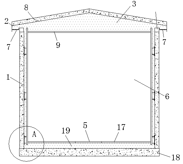
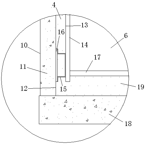
[0038] See attached figure 1 , the prefabricated cabin with breathing function includes a wall 1, a cabin roof 2 and a cabin bottom 17, a top air layer 3 is formed in the cabin roof 2, a wall air layer 4 is formed in the wall 1, and the wall air layer 4 and the top air layer 3 communicate, the base 18 is below the bilge 17, the bottom air layer 19 is formed between the bilge 17 and the base 18, the bottom air layer 19 communicates with the wall air layer 4, the bilge breathing port 5 is set on the bilge 17, and the bilge The breathing port 5 communicates with the prefabricated cabin body 6 and the bottom air layer 19 . The position of the eaves of the cabin roof 2 is provided with a cabin roof breathing port 7, and the cabin roof breathing port 7 communicates with the outside of the pr...


PUM


Abstract

The invention relates to the technical field of electric equipment, and discloses a prefabricated cabin with a breathing function. The prefabricated cabin with the breathing function includes a wall body, a cabin roof and a cabin bottom; a top air layer is formed at the cabin roof, a wall body air layer is formed in the wall body, and the wall body air layer is in communication with the top air layer; the bottom of the wall body is provided with cabin bottom breathing ports communicating with the wall body air layer, and the cabin bottom breathing ports are connected to the prefabricated cabinbody; and the entablature location of the cabin roof is provided with cabin roof breathing ports that communicates with the top air layer, and the cabin roof breathing ports are in communication withthe exterior of the prefabricated cabin. According to the invention, the breathing function of the prefabricated cabin is realized through the wall body air layer of the wall body, the bottom air layer of the cabin bottom, the top air layer of the cabin roof, the cabin roof breathing ports and the cabin bottom breathing ports, so as to improve the thermal environment inside the cabin, prevent thetemperature from rising or falling rapidly, shorten the working time of the air conditioning equipment and reduce the energy consumption.

Description

technical field [0001] The invention relates to the technical field of electric equipment, in particular to a prefabricated cabin with breathing function. Background technique [0002] The modular intelligent prefabricated cabin substation has the advantages of safety and reliability, small footprint, short construction period, small and exquisite appearance, long service life, no radiation, low noise, and flexible layout. In the application process, it has gradually been widely recognized by the market. In order to make the prefabricated cabin have a better thermal environment and improve the efficiency of the HVAC system, the structural design of the cabin has become a very research topic. [0003] Because the temperature environment of too cold or too hot may cause the electrical equipment in the prefabricated cabin to fail to operate normally. Therefore, in special areas such as high temperature / high cold / high humidity areas, air conditioning equipment is required in t...

Claims


Application Information

Patent Timeline
Patent Type & Authority Applications(China)
IPC IPC(8): E04H5/04E04B2/00E04B1/94E04B1/76A62B31/00
CPCA62B31/00E04B1/7608E04B1/7612E04B1/942E04B2/00E04H5/04
Inventor 燕飞飞许天元王说说何显江叶陈
Owner 无锡固亚德电力设备有限公司
Why Eureka
Try Eureka