Optical module

A technology of optical modules and optical fibers, which is applied in the field of optical modules, can solve problems such as the difficulty of achieving high output and difficult alignment when gathering

Inactive Publication Date: 2019-10-11
THE FUJIKURA CABLE WORKS LTD
View PDF7 Cites 2 Cited by
  • Summary
  • Abstract
  • Description
  • Claims
  • Application Information

AI Technical Summary

Problems solved by technology

However, light emitted from a laser diode is less collimated along the slow axis than the fast axis
Therefore, in the optical module described in the above-mentioned Patent Document 2, it may be difficult to gather the light emitted from the plurality of laser diodes into a narrow area, and it may be difficult to achieve high output.

Method used


Image

  • Optical module
  • Optical module
  • Optical module

Examples


no. 1 approach

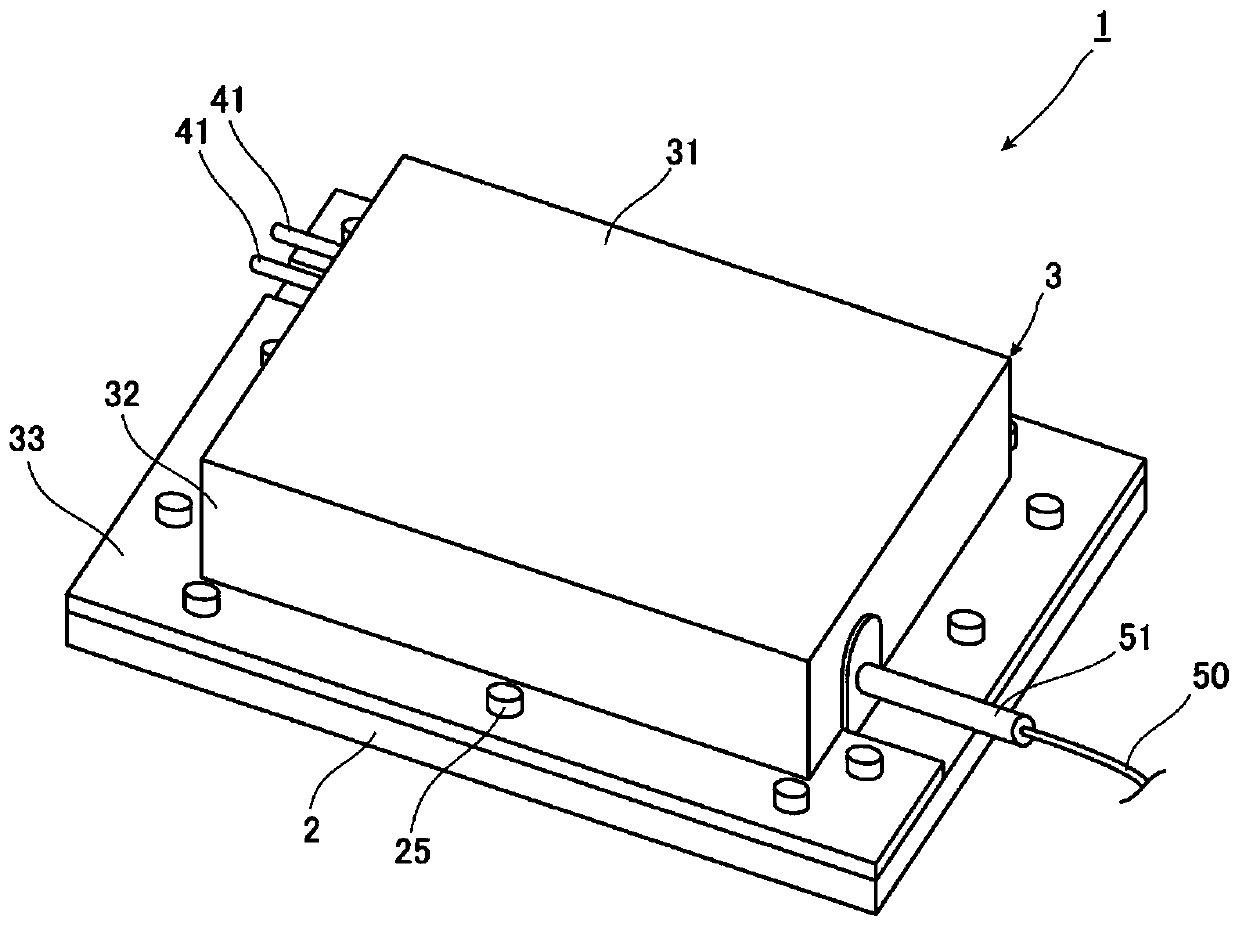
[0045] figure 1 It is a perspective view showing the optical module according to this embodiment. Such as figure 1As shown, the optical module 1 of the present embodiment includes: a housing composed of a base plate 2 and a cover 3; the following optical components fixed in the housing; and a connector 41 for supplying power to some of the optical components. .

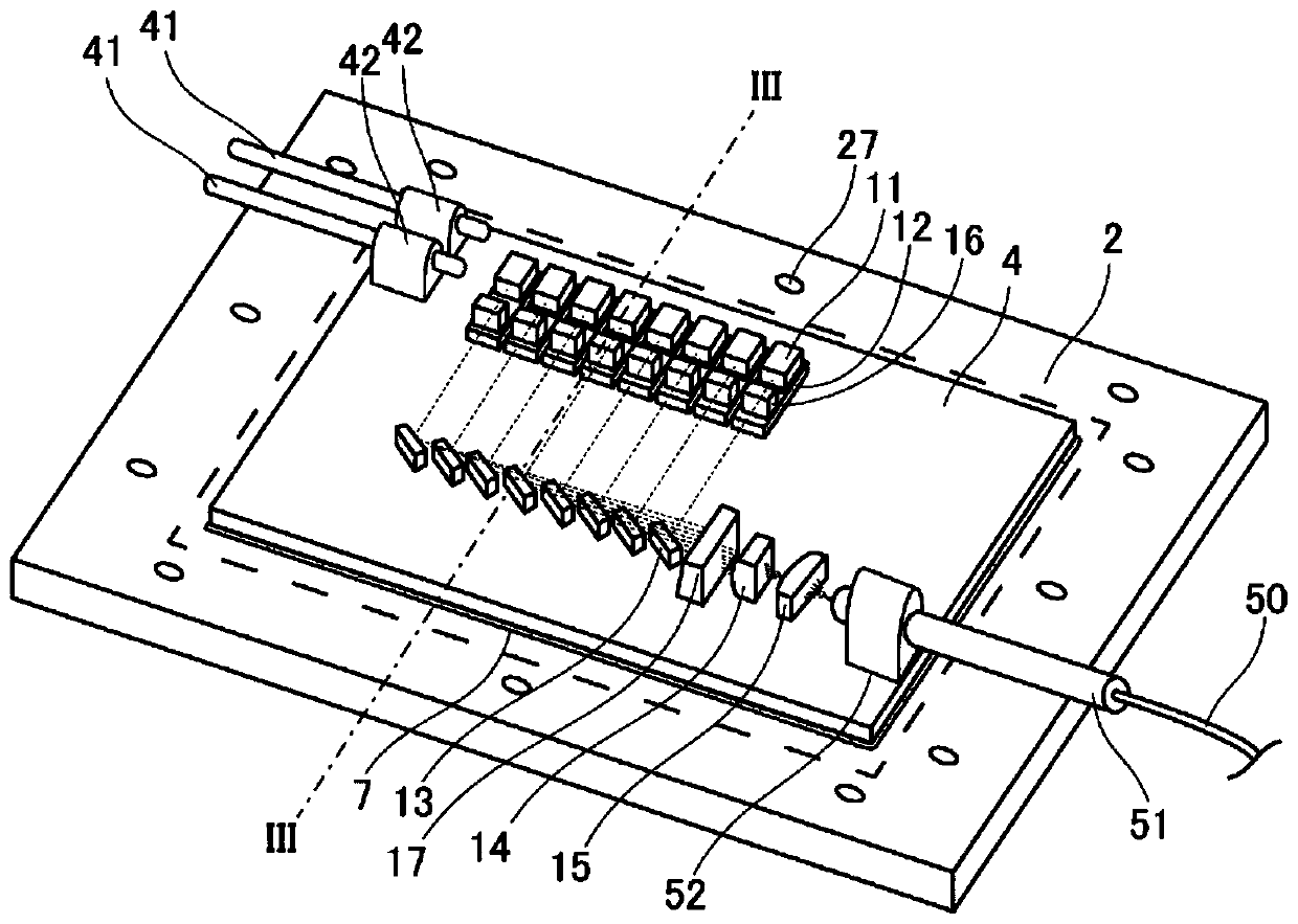
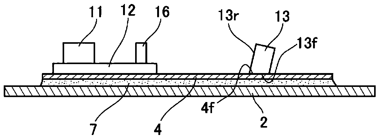
[0046] figure 2 will be figure 1 It is a figure showing that the cover body 3 of the optical module 1 is removed. exist figure 2 In , the optical path of the light emitted from the laser diode 11 is indicated by a dotted line. in addition, image 3 is along figure 2 A cross-sectional view of the optical module 1 along line III-III shown.

[0047] The base plate 2 is a plate with a planar bottom as the bottom plate of the housing. In this embodiment, as figure 2 and image 3 As shown, it is a flat part. The base plate 2 is made of metal, and examples of the metal constituting the base plate 2 include co...

no. 2 approach

[0078] Next, refer to Figure 7 A second embodiment of the present invention will be described in detail. In addition, about the same or equivalent components as those of the first embodiment, unless otherwise specified, the same reference numerals are attached, and overlapping descriptions are omitted.

[0079] Figure 7 so with Figure 5 The same viewpoint shows the diagram of the optical module according to this embodiment. The optical module 1 a of this embodiment differs from the first embodiment in that it does not include the light refraction member 17 . In addition, since the optical module 1 a does not include the light refraction member 17 , the arrangement of the first condenser lens 14 , the second condenser lens 15 , and the optical fiber 50 is different from that of the first embodiment. In this embodiment, the optical axes of the first condenser lens 14, the second condenser lens 15, and the optical fiber 50 are inclined relative to the surface on which the ...

no. 3 approach

[0081] Next, refer to Figure 8 and Figure 9 A third embodiment of the present invention will be described in detail. In addition, about the same or equivalent components as those of the second embodiment, unless otherwise specified, the same reference numerals are attached, and overlapping descriptions are omitted.

[0082] Figure 8 so with Figure 5 The same viewpoint shows the diagram of the optical module according to this embodiment. Figure 9 will be Figure 8 Shown is an enlarged cross-sectional view of the end of the optical fiber. exist Figure 9 In , the arrow L2 indicates the direction of light propagation. The arrangement of the optical fiber 50 and the shape of the incident end of the optical module 1 b of this embodiment are different from those of the second embodiment. The optical fiber 50 of the present embodiment is arranged such that the optical axis of the optical fiber 50 is parallel to the plane on which the plurality of laser diodes 11 are arra...


PUM


Abstract

An optical module (1) is provided with: laser diodes (11) that are a plurality of light emitting elements disposed on a same plane; and a plurality of mirrors (13) that reflect beams outputted from respective laser diodes (11). The mirrors (13) reflect the beams in the direction tilted with respect to the plane on which the laser diodes (11) are disposed, said beams having been outputted from respective laser diodes (11), and align the beams with each other in the fast-axis direction.

Description

technical field [0001] The present invention relates to optical modules. Background technique [0002] As one of the optical modules, it is known that light emitted from a laser diode is emitted through an optical fiber. In this optical module, an optical fiber is led out from the inside of the housing, and optical components such as a laser diode, a mirror, a lens, and an optical fiber are arranged in the housing. The light emitted from each laser diode enters the optical fiber after being condensed, and is emitted from the optical fiber outside the housing. [0003] For example, in the following patent document 1, the following optical module is disclosed. A condensing lens that collects light reflected by a mirror and enters it into an optical fiber. [0004] In addition, the following patent document 2 discloses an optical module including: a plurality of laser diodes arranged on the same plane; a collimator for collimating the light emitted from each laser diode; a ...

Claims


Application Information

Patent Timeline
Patent Type & Authority Applications(China)
IPC IPC(8): G02B6/42H01S5/022H01S5/0239
CPCG02B6/4206G02B6/4214G02B27/0922G02B27/0905G02B27/0977G02B27/0955G02B19/0057H01S5/4012G02B6/4267H01S5/02208H01S5/02325H01S5/02251H01S5/0239G02B19/0028H01S5/0071
Inventor 葛西洋平
Owner THE FUJIKURA CABLE WORKS LTD
Why Eureka
Try Eureka