Laser reflow device

一种回流焊、激光的技术,应用在激光焊接设备、焊接设备、焊接设备等方向,能够解决激光照射部无法使用、长更换时间等问题,达到减少焊接作业等待时间、提高生产性、减少焊接不良率的效果

Active Publication Date: 2019-10-11
LASERSSEL CO LTD
View PDF10 Cites 3 Cited by
  • Summary
  • Abstract
  • Description
  • Claims
  • Application Information

AI Technical Summary

Problems solved by technology

[0009] In the conventional laser reflow soldering equipment, the pressure head and the laser irradiation part are integrally formed. Therefore, if the pressure head is damaged, the laser irradiation part cannot be used.
In addition, in order to replace a damaged pressurizing head, it is necessary to disassemble the pressurizing head and the laser irradiation part as a whole, so a long replacement time is required

Method used


Image

  • Laser reflow device
  • Laser reflow device
  • Laser reflow device

Examples


Embodiment Construction

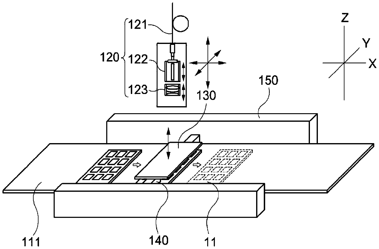
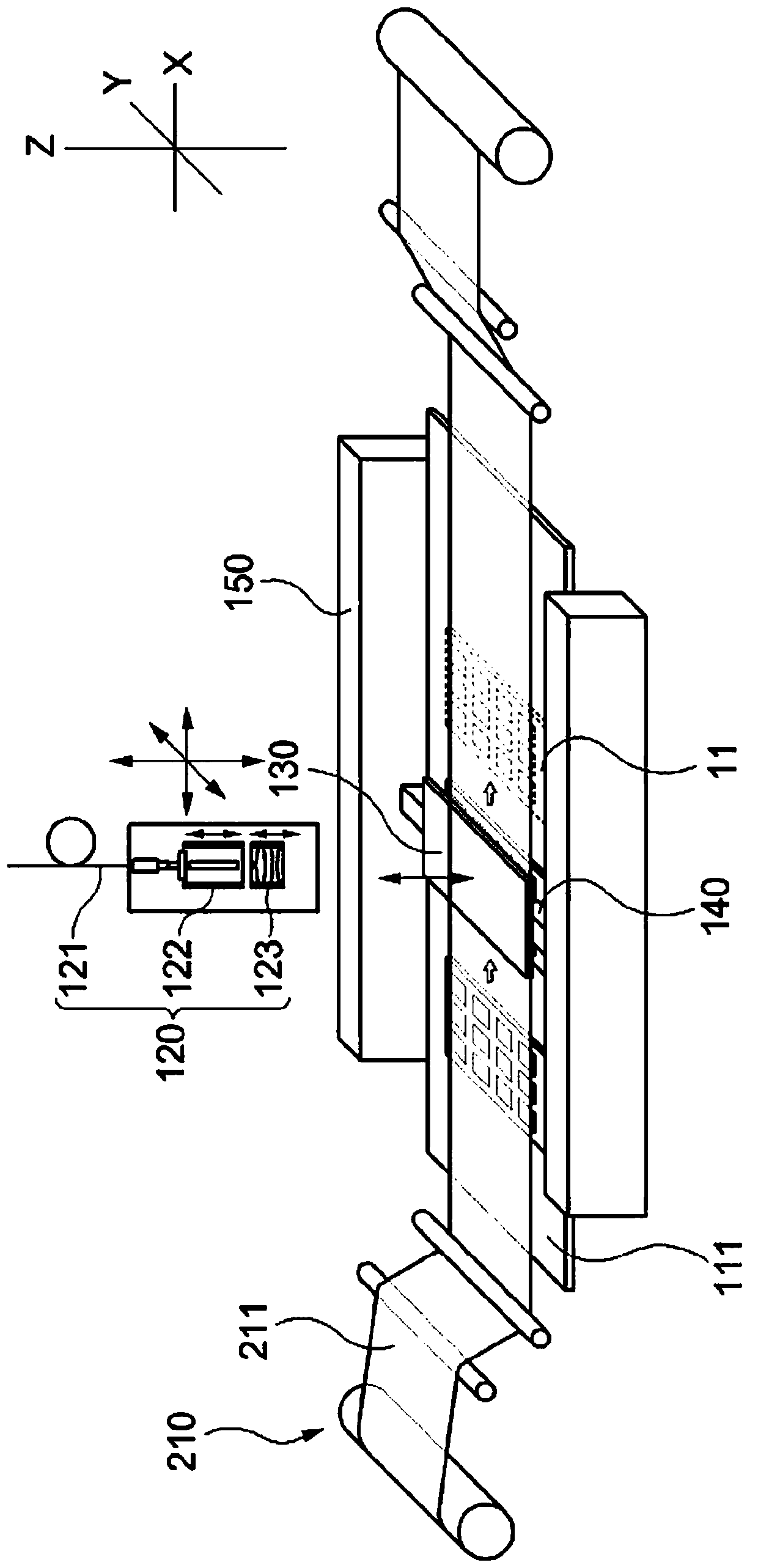
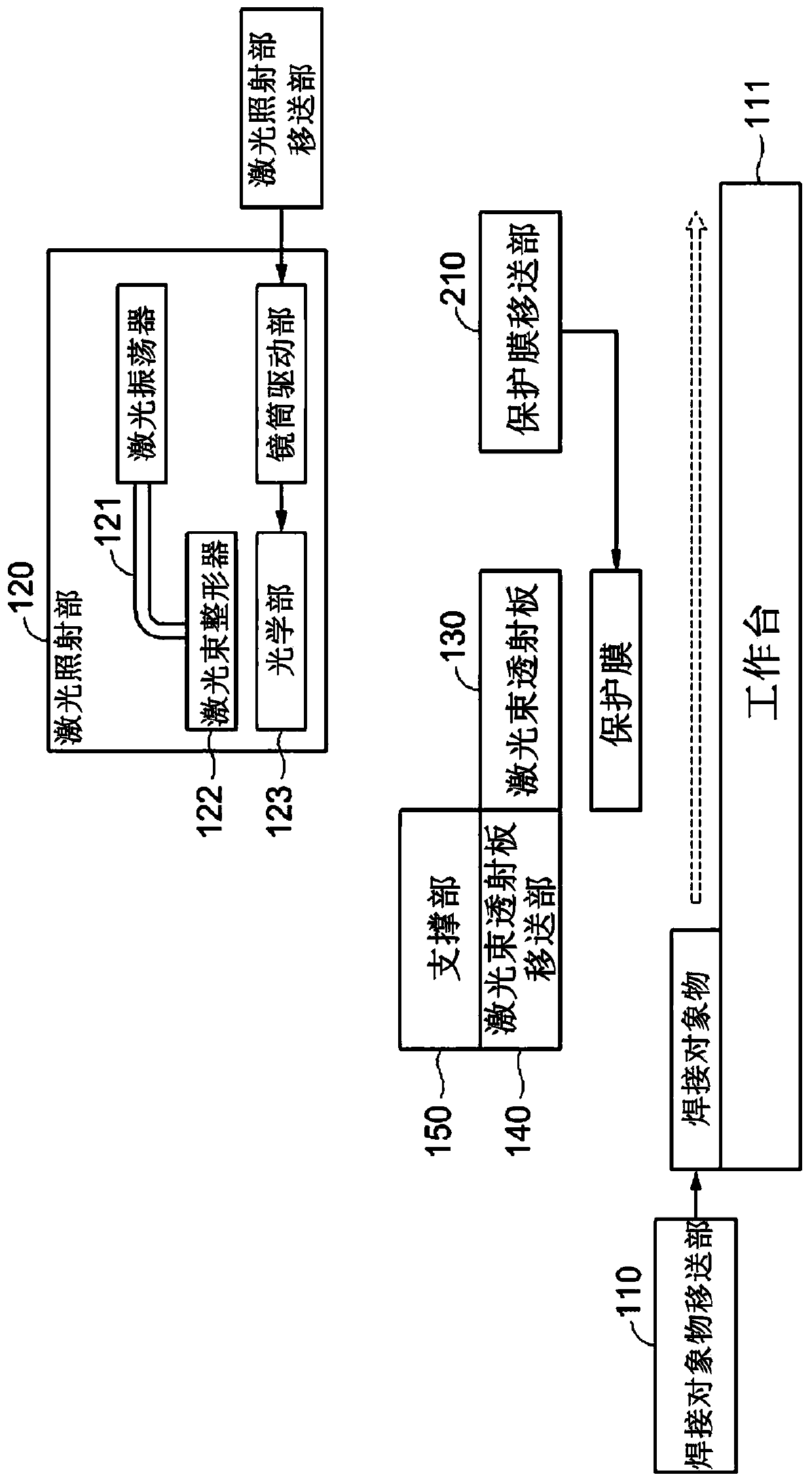
[0048]The terms used in this specification are used to describe specific embodiments only, and are not used to limit the present invention. Expressions in the singular include expressions in the plural as long as the context does not clearly indicate otherwise. In this specification, terms such as "comprising" or "having" are used to designate the existence of features, numbers, steps, actions, structural elements, components or combinations thereof described in this specification, rather than to preclude one or more than one The existence or additional possibility of other features or numbers, steps, actions, structural elements, components or combinations thereof.

[0049] Unless otherwise defined, all terms used in this specification including technical or scientific terms have the same meaning as commonly understood by one of ordinary skill in the art to which this invention belongs. Terms defined by commonly used dictionaries have the same meanings as those in the contex...


PUM

PropertyMeasurementUnit
visible light transmittanceaaaaaaaaaa

Abstract

The present invention relates to a laser reflow device, which can implement shortening of a tact time for one object to be bonded and the acceleration of a bonding operation for all of the plurality of objects to be bonded and comprises: an object-to-be-bonded transferring part including a stage for supporting the object to be bonded, and transferring the object to be bonded; a laser emitting partfor converting a laser into a surface light source form and emitting the same to the object to be bonded, and a laser emitting part transferring part for moving the laser emitting part to an emissionposition or a standby position; and a beam-transmitting plate independently provided separately from the laser emitting part and allowing the laser having the surface light source form to pass therethrough, and a beam-transmitting plate transferring part for moving the beam-transmitting plate to an operation position or the standby position.

Description

technical field [0001] The present invention relates to a laser reflow soldering device. More specifically, it relates to a method capable of shortening the tact time (tact time) for one object to be welded, realizing high-speed soldering operations for the entirety of a plurality of objects to be welded, and eliminating problems caused by stacking or warpage. (Warpage) A laser reflow soldering device that speeds up the welding operation of the welding object that requires pressure. Background technique [0002] In general, a pressure-type reflow soldering apparatus solders a thin silicon wafer to a substrate by applying pressure and temperature to the silicon wafer by approaching the silicon wafer with a head heated to a predetermined temperature. Wherein, one head is in contact with a silicon chip, and the heat conduction of the heated head is used to irradiate heat to the reflow part of the lower part of the silicon chip, and the heat conduction time needs at least severa...

Claims


Application Information

Patent Timeline
Patent Type & Authority Applications(China)
IPC IPC(8): H01L21/67B23K26/20B23K103/00
CPCB23K26/20B23K2103/56H01L21/67132H01L21/67144B23K1/0056B23K26/0648B23K26/073B23K26/0738B23K26/0884B23K26/0838B23K26/16B23K26/706
Inventor 崔在浚金秉喆金秉禄金南成
Owner LASERSSEL CO LTD
Why Eureka
Try Eureka