
A portable device and method for measuring power-law fluid flow parameters

A power-law fluid and flow parameter technology, which is applied in the field of portable devices for measuring power-law fluid flow parameters, can solve problems such as the inability to measure the flow characteristics of non-Newtonian fluids in real time, the large size of the measuring device, and the complex experimental system.

Active Publication Date: 2021-01-19
XI AN JIAOTONG UNIV
View PDF14 Cites 0 Cited by
  • Summary
  • Abstract
  • Description
  • Claims
  • Application Information

AI Technical Summary

Problems solved by technology

The capillary method uses high-pressure gas to generate a pressure difference to drive the power-law fluid to flow in the capillary. The obtained flow rate is a function of the pressure difference and the flow parameter. According to the corresponding functional relationship, the flow parameter of the power-law fluid is calculated by measuring the flow rate; this system requires high pressure. Gas source, complex experimental system, high cost
The rotation method measures the torsion torque, and then determines the flow parameters according to the functional relationship between the torque and the power law fluid flow parameters; this method has mechanical rotating parts, and the stability is poor
In addition, the measurement devices based on the above two methods are large in size, inconvenient to move, and unable to measure the flow characteristics of non-Newtonian fluids in real time

Method used

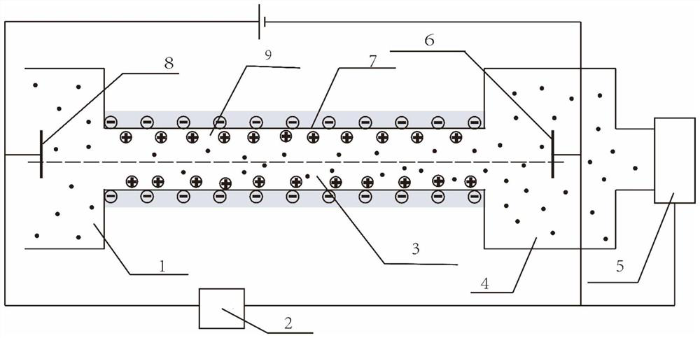

Image

  • A portable device and method for measuring power-law fluid flow parameters
  • A portable device and method for measuring power-law fluid flow parameters
  • A portable device and method for measuring power-law fluid flow parameters

Examples


Embodiment Construction

[0048] The present invention will be further described in detail below in conjunction with the accompanying drawings. The present invention discloses a device and method for measuring power-law fluid flow parameters.

[0049] see figure 1, the device includes two power-law fluid first storage tank 1 and second storage tank 4, these two storage tanks are communicated by microchannel 3, the first storage tank 1 and second storage tank 4 are large enough compared to the microchannel , so as to stabilize the fluid flow in the microchannel 3; the physical and chemical action caused by the contact of the power law fluid in the microchannel 3 with the microchannel wall 7 makes the microchannel wall 7 electrified, thereby close to the microchannel wall 7 Electric double layer 9 is formed in the power-law fluid; Positive electrode 8 is placed in the first storage box 1 at the entrance of the microchannel, and negative electrode 6 is placed in the second storage box 4 at the outlet of t...


PUM


Abstract

The invention discloses a portable device and method for measuring a power-law fluid flow parameter. Two storage boxes for storing the power-law fluids are arranged at two ends of a micro-channel, andone electrode is arranged in each storage box; an axial electric field is formed in the micro-channel by applying voltage between two electrodes, and then the power-law fluid is driven to produce electro-osmosis flow in the microchannel; by regulating the voltages at two ends of the channel, the axial electric field strength in the micro-channel is changed, thereby causing the volume flow rate change of the power-law fluid in the micro-channel; by measuring the volume flow rate on the power-law fluid under different voltage values, the consistence coefficient and the flow index of the power-law fluid can be finally determined according to a dependency relation among the voltage, the flow rate and the flow parameter. The device does not relate to a mechanical rotating component, the mechanical damage is less, the miniaturization and portability are realized, and the required testing sample amount is reduced; since the fluid driving and the flow rate measurement adopt the electric signal, the device data collection and processing are extremely convenient, and the automatic measurement can be conveniently realized.

Description

【Technical field】 [0001] The invention belongs to the field of physical parameter measurement, and in particular relates to a portable device and method for measuring flow parameters of power-law fluids. 【Background technique】 [0002] Non-Newtonian fluids play an important role in human production and life and in nature. Therefore, it is extremely important to understand the basic characteristics of non-Newtonian fluids, which will greatly promote the progress of production and life. The characteristics of non-Newtonian fluids are different from Newtonian fluids, and will change with the change of flow state. This complexity makes it a difficult problem to measure the flow parameters of non-Newtonian fluids quickly and accurately. Most non-Newtonian fluids can be regarded as power-law fluids, so how to determine the flow parameters of power-law fluids, that is, the consistency coefficient and fluidity index, becomes the key to determine the flow characteristics of non-Newto...

Claims


Application Information

Patent Timeline
Patent Type & Authority Patents(China)
IPC IPC(8): G01F1/64G01D21/02
CPCG01D21/02G01F1/64
Inventor 赵存陆黄灯钱芳王秋旺
Owner XI AN JIAOTONG UNIV
Learn More