Eureka AIR delivers breakthrough ideas for toughest innovation challenges, trusted by R&D personnel around the world.

Bandwidth-enhanced compact microstrip antenna based on dual-mode fusion and wireless communication system

A microstrip antenna, compact technology, applied in the direction of antenna, antenna grounding device, antenna grounding switch structure connection, etc., can solve the problems of complex structure, low gain, large cross polarization and other problems of two antennas, and achieve easy realization and processing, The effect of reducing physical size and enhancing antenna bandwidth

Active Publication Date: 2019-10-15
XIDIAN UNIV
View PDF7 Cites 4 Cited by
  • Summary
  • Abstract
  • Description
  • Claims
  • Application Information

AI Technical Summary

Problems solved by technology

[0005] (1) The thickness of an antenna in the prior art is 0.026λ 0 , but the processing cost is high, and the bandwidth is only 1%
[0006] (2) The structure of the second antenna in the prior art is complicated, the processing difficulty is increased, and the cross polarization is large, and the gain is low
[0007] (3) The bandwidth of the three antennas in the prior art is only 1%
However, the narrow-band characteristic is a significant disadvantage that limits its application development.

Method used


Image

  • Bandwidth-enhanced compact microstrip antenna based on dual-mode fusion and wireless communication system
  • Bandwidth-enhanced compact microstrip antenna based on dual-mode fusion and wireless communication system
  • Bandwidth-enhanced compact microstrip antenna based on dual-mode fusion and wireless communication system

Examples


Embodiment Construction

[0040] In order to make the object, technical solution and advantages of the present invention more clear, the present invention will be further described in detail below in conjunction with the examples. It should be understood that the specific embodiments described here are only used to explain the present invention, not to limit the present invention.

[0041] Aiming at the problem that the existing microstrip antenna has large size, complex structure and narrow bandwidth, which hinders the application of the antenna in communication, aerospace and other systems. The invention not only ensures the compact structure of the microstrip antenna, but also enhances the bandwidth, has a simple structure and is easy to process and manufacture.

[0042] The application principle of the present invention will be described in detail below in conjunction with the accompanying drawings.

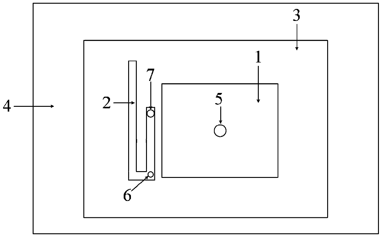
[0043] Such as figure 1 As shown, the bandwidth-enhanced compact microstrip antenna based on dua...


PUM


Abstract

The invention belongs to the technical field of wireless communication and discloses a bandwidth-enhanced compact microstrip antenna based on dual-mode fusion and a wireless communication system. A rectangular radiation microstrip and an L-shaped radiation microstrip are attached to a dielectric substrate and are located on a topmost layer of the antenna; the dielectric substrate is located on a middle layer of the bandwidth-enhanced compact microstrip antenna based on dual-mode fusion; a metal floor is located on a lower layer of the dielectric substrate; a gap is formed between the rectangular radiation microstrip and the L-shaped radiation microstrip for radiating linearly polarized electromagnetic waves; short circuit pins are arranged in the center of the rectangular radiation microstrip and at the corner of the L-shaped radiation microstrip respectively; and the metal floor is located at the bottommost place of the whole antenna, and is equipped with a radio-frequency connector.The bandwidth-enhanced compact microstrip antenna solves the problem of narrow bandwidth of a traditional microstrip antenna under the condition of compact structure, has a unipolar radiation patternwhile ensuring antenna gain, and can be better applied to the wireless communication system.

Description

technical field [0001] The invention belongs to the technical field of wireless communication, and in particular relates to a bandwidth-enhanced compact microstrip antenna and a wireless communication system based on dual-mode fusion. Background technique [0002] Due to its small size, light weight, and easy integration with wireless devices, microstrip antennas have been used more and more in modern wireless communication technologies. With the development of modern communication technology, the requirements for the design of microstrip antenna are becoming more and more stringent, and it must have a wider bandwidth while ensuring its compact structure. Therefore, it is of practical significance to study compact microstrip antennas with bandwidth enhancement capabilities. However, the relative bandwidth of the traditional microstrip antenna is generally only about 1%, and if the size of the antenna is to be reduced, the bandwidth of the antenna may be narrower. Therefore...

Claims


Application Information

Patent Timeline
Patent Type & Authority Applications(China)
IPC IPC(8): H01Q1/38H01Q1/48H01Q1/50H01Q5/10H01Q5/307
CPCH01Q1/38H01Q1/48H01Q1/50H01Q5/10H01Q5/307
Inventor 刘能武贾智慧傅光祝雷
Owner XIDIAN UNIV
Why Eureka
Eureka Blog
Learn More