A device and method for controlling the volumetric flow rate of a power-law fluid in a microchannel

A power-law fluid, volumetric flow technology, applied in the field of microfluidics, which can solve problems such as pressure difference, difficulty in precise control of fluid flow, and low drive efficiency

Active Publication Date: 2021-01-19
XI AN JIAOTONG UNIV
View PDF11 Cites 0 Cited by
  • Summary
  • Abstract
  • Description
  • Claims
  • Application Information

AI Technical Summary

Problems solved by technology

Although the traditional fluid control technology based on pumps and valves has achieved certain applications in the field of microfluidics, it has many shortcomings and is inconvenient for popularization and application.
For example, due to the strict limitation of space in microfluidic applications, the arrangement of traditional pumps and valves is very inconvenient; in addition, traditional pumps have rotating parts, which are noisy and have poor flow stability, making it difficult to achieve precise control of fluid flow; finally, traditional The driving force of the pump comes from the pressure difference, and the driving efficiency is low in micro-nano channels

Method used


Image

  • A device and method for controlling the volumetric flow rate of a power-law fluid in a microchannel
  • A device and method for controlling the volumetric flow rate of a power-law fluid in a microchannel
  • A device and method for controlling the volumetric flow rate of a power-law fluid in a microchannel

Examples


Embodiment Construction

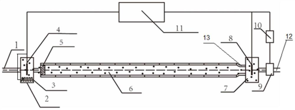
[0042] The present invention will be described in further detail below with reference to the accompanying drawings. The present invention discloses a device and method for controlling the volumetric flow rate of a power-law fluid in a microchannel; see figure 1, the device includes an input pipeline 1, an inlet storage tank 2, a temperature regulator 3, a positive electrode 4, a micro-flow stabilization device 5, a microchannel 6, an outlet storage tank 7, a negative electrode 8, a flow meter 9, an arithmetic unit 10, a control And the data processing system 11 , the output pipe 12 and the arc pipe 13 .

[0043] see figure 1 , the two ends of the microchannel 6 are respectively communicated with the input pipeline 1 and the output pipeline 12, an inlet storage tank 2 is arranged between the input pipeline 1 and the inlet of the microchannel 6, and a temperature regulator 3 and a positive electrode 4 are placed in the inlet storage tank 2. , the inlet of the micro-channel 6 is...


PUM


Abstract

The invention discloses a device and method for controlling the volume flow of a power-law fluid in a microchannel. The power-law fluid contacts the solid wall surface of the microchannel, and the solid surface can acquire electric charge because of specific physical and chemical reactions. The electric charge on the microchannel solid surface can affect the distribution of ions in the power-law fluid and form an electrical double layer in the power-law fluid near the wall surface. Under the action of an external electric field, the power-law fluid in the electrical double layer produces electroosmotic flow. By solving a control equation for the flow of the power-law fluid in the microchannel, the velocity distribution of electroosmotic flow in the microchannel can be obtained, and then the volume flow of the power-law fluid in the microchannel can be worked out. By adjusting the voltage, precise regulation of the volume flow of the power-law fluid in the microchannel can be realized.An electric field is added at both ends of the microchannel, and under the action of the electric field, the power-law fluid is driven to move in the microchannel. The device has a simple structure and no rotating part, and reduces vibration and noise.

Description

【Technical field】 [0001] The invention belongs to the technical field of microfluidics, and in particular relates to a device and method for controlling the volume flow of a power-law fluid in a microchannel. 【Background technique】 [0002] With the rapid development of social production, the requirements for equipment performance have increased sharply, and the miniaturization of equipment is also required; in this case, microfluidic technology came into being. Microfluidic technology has important applications in the fields of integrated circuit cooling, biochemical analysis systems, drug testing and new energy; in these important applications, how to precisely control the transport of fluids in microchannels is a common key issue. At present, the expansion of practical applications has led to an increasingly obvious trend of using non-Newtonian fluids as flow media. For example, the lab-on-a-chip based on microfluidic technology is mainly used to analyze and process vario...

Claims


Application Information

Patent Timeline
Patent Type & Authority Patents(China)
IPC IPC(8): B01L3/00
CPCB01L3/50273B01L3/502746B01L2200/0605B01L2200/0636B01L2400/0418
Inventor 赵存陆黄灯钱芳王秋旺
Owner XI AN JIAOTONG UNIV
Why Eureka
Try Eureka