Hydraulic drive internal combustion engine

A technology of hydraulic transmission and internal combustion engine, applied in the direction of machines/engines, mechanical equipment, etc., can solve problems such as incompleteness, achieve the effects of low noise, reduce friction loss, and improve mechanical efficiency

Inactive Publication Date: 2003-03-19
赵硕颀
View PDF2 Cites 0 Cited by
  • Summary
  • Abstract
  • Description
  • Claims
  • Application Information

AI Technical Summary

Problems solved by technology

But due to various reasons, mainly due to the solution of technical problems, it has not been perfected, so far there has not bee

Method used


Image

  • Hydraulic drive internal combustion engine
  • Hydraulic drive internal combustion engine
  • Hydraulic drive internal combustion engine

Examples


Embodiment Construction

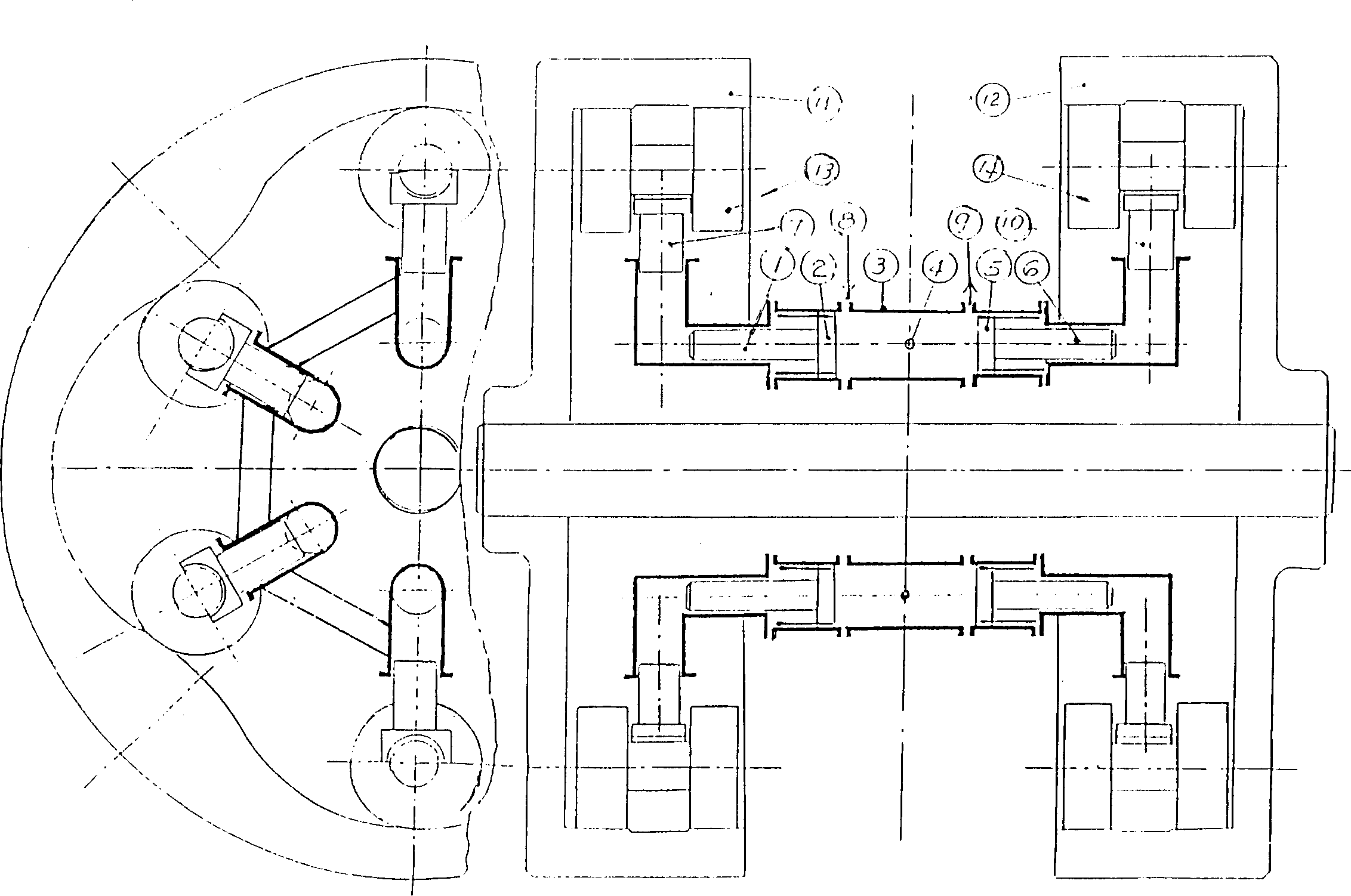
[0019] The whole machine consists of several units (attached figure 1 ), the middle is the internal combustion cylinder, the two sides are the hydraulic cylinder, and the two ends are the intake end cam and the exhaust end cam. The units are arranged symmetrically with respect to the cam.

[0020] The unit structure is attached Figure 1 , of which 1 is the hydraulic pump plunger at the intake end, 2 is the intake end piston, 3 is the cylinder, 4 is the fuel injection nozzle, 5 is the exhaust end piston, 6 is the exhaust end pump plunger, and 7 is the intake end Hydraulic motor plunger, 8 is the intake port, 9 is the exhaust port, 10 is the exhaust end motor plunger, 11 is the intake end cam, 12 is the exhaust end cam, 13 and 14 are the rollers.

[0021] When the two pistons 2 and 5 are close to the inner dead center position, the fuel injection nozzle 4 catches fire and burns, the pressure in the cylinder 3 rises, and pushes the pistons 2 and 5 and the pump plungers 1 and 6...


PUM


Abstract

A new-type IC engine with hydraulic drive other than crank-connecting rod mechanism is composed of opposed piston cylinders, plunger pumps at both ends, and plunger-type internal or external curved oil motor unit. The cam curve can control and optimize the speed distribution of opposed pistons. Said hydraulic cylinder has liquid supplementing, cooling and liquid replacing mechanisms.

Description

Technical field: [0001] The invention belongs to an internal combustion engine which replaces a crank connecting rod mechanism with hydraulic transmission. Background technique: [0002] The internal combustion engine adopts a crank connecting rod mechanism to convert the reciprocating motion of the piston into a rotary motion, which is a fixed and unchanged tradition for hundreds of years. However, the crank connecting rod mechanism is not perfect. It has many inherent and insurmountable limitations. For example, the movement law of the piston is limited by the transformation of the circular motion, it is impossible to design according to the optimization requirements, the moving parts cannot be completely balanced, and the number of friction parts is large, etc. etc., so that the development of internal combustion engines is limited. Therefore, over the years, there have been various ideas and trials to replace the crank connecting rod mechanism in other forms, such as ro...

Claims


Application Information

Patent Timeline
IPC IPC(8): F02B75/32
Inventor 赵硕颀
Owner 赵硕颀
Why Eureka
Try Eureka