Sedimentation tank for water treatment

A sedimentation tank, water treatment technology, applied in water/sewage multi-stage treatment, water/sludge/sewage treatment, filtration treatment, etc., can solve interference, slow down the speed of flocculation and gravitational sedimentation, stirring and mixing effect Poor and other problems, to achieve the effect of accelerating aggregation and decline

Inactive Publication Date: 2019-10-18
侯文俊
View PDF0 Cites 11 Cited by
  • Summary
  • Abstract
  • Description
  • Claims
  • Application Information

AI Technical Summary

Problems solved by technology

[0003] The traditional sedimentation tank is equipped with a stirring plate to make the flocculant contact with the suspended matter in the sewage, but it interferes with the flocculated sediment, slows down the flocculation of the sediment and the speed of gravity settlement, resulting in poor mixing effect

Method used


Image

  • Sedimentation tank for water treatment
  • Sedimentation tank for water treatment
  • Sedimentation tank for water treatment

Examples


Embodiment 1

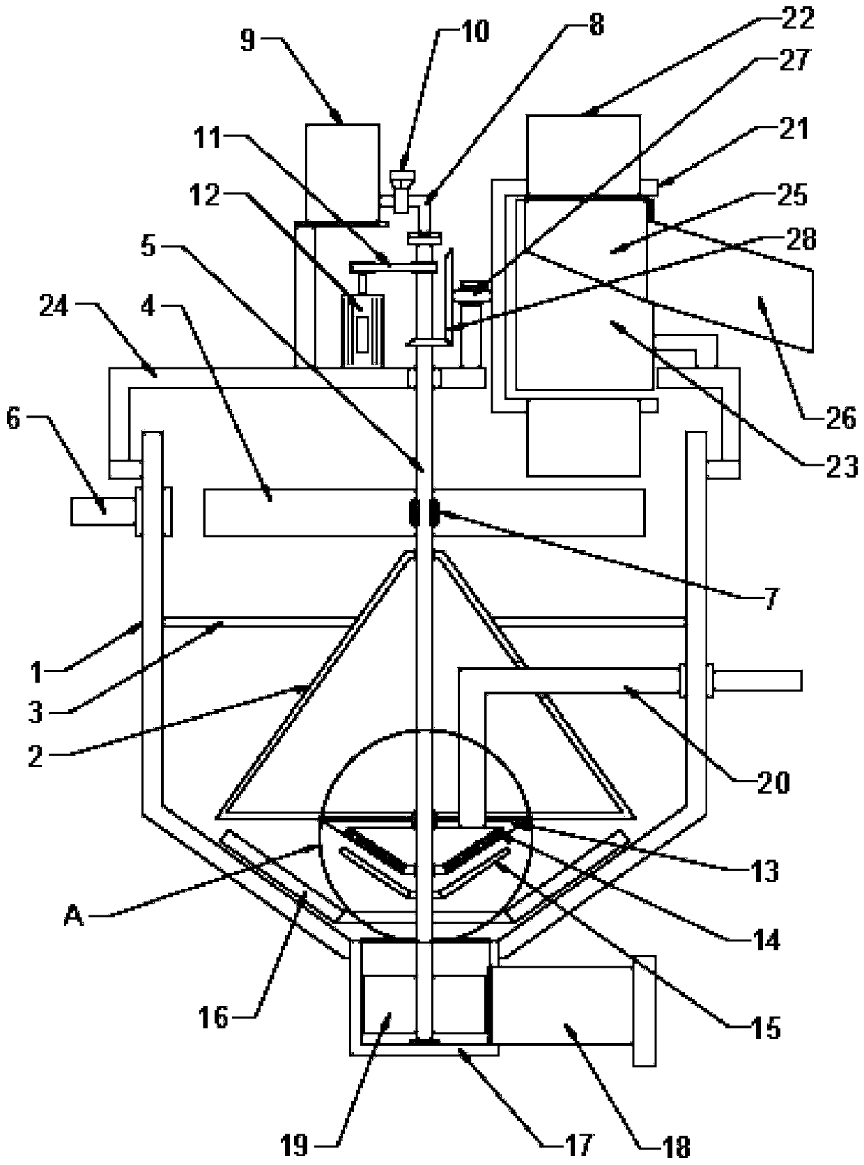
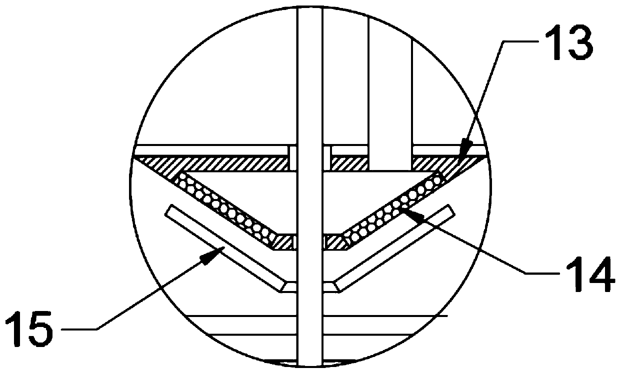
[0024] see Figure 1-5 , in an embodiment of the present invention, a sedimentation tank for water treatment includes a tank body 1; a conical cylinder 2 is arranged inside the tank body 1, and the conical cylinder 2 is fixedly connected to the inner wall of the tank body 1 through a fixing rod 3; Above the conical cylinder 2, there are agitating plates 4 distributed in a circle. The agitating plates 4 are fixedly connected with a rotating shaft 5, and the rotating shaft 5 extends to the top of the pool body 1 and is connected with a driving motor 12 through a transmission belt 11. The driving motor 12 is fixedly connected with a Bridge frame 24, bridge frame 24 is fixedly connected with pool body 1; Nozzle 7 is arranged between said stirring plate 4, Nozzle 7 is fixedly connected with rotating shaft 5, An infusion tube 8 is nested in the rotating shaft 5, The lower end of the infusion tube 8 communicates with the nozzle 7 , the infusion tube 8 extends to the top of the rotati...

Embodiment 2

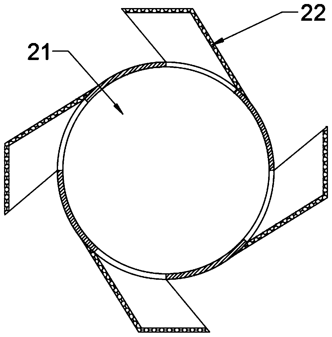
[0029] The difference between this embodiment and Embodiment 1 is that a salvage mechanism is provided on the upper part of the pool body 1, and the salvage mechanism includes an overshot cylinder 21, which is a cylindrical cylinder with an opening at one end, and the overshot cylinder 21 is fixedly connected with salvage cylinders distributed in a circle. Bucket 22, the salvage bucket 22 is a metal mesh bucket, and the salvage bucket 22 communicates with the salvage barrel 21; the salvage barrel 21 is nested with a fixed cylinder 23 and is rotatably connected with the fixed cylinder 23, and the fixed cylinder 23 is fixedly connected with the bridge frame 24; A blanking chamber 25 is provided on the upper part of the fixed cylinder 23, and the blanking chamber 25 is connected with a slag discharge pipe 26.

[0030] The overshot 21 is fixedly connected with a transmission shaft 27, and the transmission shaft 27 is connected and driven with the rotating shaft 5 through a transmis...


PUM


Abstract

The invention discloses a sedimentation tank for water treatment, which comprises a tank body. A conical barrel is arranged in the tank body, circumferentially distributed stirring plates are arrangedabove the conical barrel, and shower nozzles are arranged among the stirring plates. According to the sedimentation tank for water treatment, through arrangements of the shower nozzles among the stirring plates and a water inlet pipe and the conical barrel located on the same plane as the stirring plates, rotational flow is generated by sewage, so that a flocculating agent can be efficiently diffused in a centrifugal mode and fully mixed with the sewage, and at the same time, accumulation and descending of the sedimentation are accelerated; a filter cartridge, a cleaning scraper plate, and acollecting scraper plate are arranged, and separation of the sedimentation and the sewage is accelerated while blockage of a sieve is avoided; and a fishing socket, a fixing barrel, and a fishing bucket are arranged, so that the swirling garbage which moves around and floats around circumferentially under the action of the rotational flow is efficiently salvaged and discharged.

Description

technical field [0001] The invention relates to the field of water treatment equipment, in particular to a sedimentation tank for water treatment. Background technique [0002] Sedimentation tank is a structure that uses sedimentation to remove suspended solids in water and is an equipment for purifying water quality. Use the natural precipitation of water or the effect of coagulation and sedimentation to remove suspended solids in water. The sedimentation tank is divided into horizontal sedimentation tank and vertical sedimentation tank according to the direction of water flow. The sedimentation effect depends on the flow rate of the water in the sedimentation tank and the residence time of the water in the tank. In order to improve the sedimentation effect and reduce the land area, honeycomb inclined tube counterflow sedimentation tanks, accelerated clarifiers, pulse clarifiers, etc. are currently used. Sedimentation tanks are widely used in wastewater treatment. [000...

Claims


Application Information

Patent Timeline
Patent Type & Authority Applications(China)
IPC IPC(8): C02F9/04
CPCC02F1/001C02F1/40C02F1/52C02F9/00C02F2303/14
Inventor 侯文俊
Owner 侯文俊
Why Eureka
Try Eureka