Heat treatment furnace for heat treatment of steel wire

A heat treatment furnace and steel wire technology, applied in heat treatment furnace, heat treatment equipment, heat treatment process control, etc., can solve the problems of high energy consumption and high price

Active Publication Date: 2020-10-27
四川圣德钢缆有限公司
View PDF8 Cites 0 Cited by
  • Summary
  • Abstract
  • Description
  • Claims
  • Application Information

AI Technical Summary

Problems solved by technology

[0006] In order to overcome the defects and deficiencies in the above-mentioned prior art, the present invention provides a heat treatment furnace for steel wire heat treatment. question

Method used


Image

  • Heat treatment furnace for heat treatment of steel wire
  • Heat treatment furnace for heat treatment of steel wire
  • Heat treatment furnace for heat treatment of steel wire

Examples


Embodiment 1

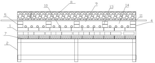
[0034] As a preferred embodiment of the present invention, with reference to the attached Figure 1-3 , this example discloses:

[0035] The heat treatment furnace used for steel wire heat treatment, the heat treatment furnace in this embodiment can be used for the drying furnace in the steel wire production process, refer to the attached figure 1 , the heat treatment furnace of the present embodiment includes a furnace body 1, a furnace body support 2 and a power distribution cabinet 3 supported under the furnace body 1, and the furnace body 1 includes a furnace body 1 shell, a steel wire inlet 4 and a steel wire outlet 5 The four side walls and the bottom of the shell of the furnace body 1 are provided with ceramic fiber boards 6, and at least three layers of lightweight bricks 7 are laid on the top of the bottom ceramic fiber boards 6, and the ceramic fiber boards 6 of the four side walls of the shell of the furnace body 1 The inner side is laid with lightweight bricks 7,...

Embodiment 2

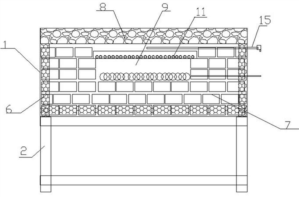
[0040] As another preferred embodiment of the present invention, with reference to the attached Figure 4-6 As shown, the present embodiment discloses:

[0041] The heat treatment furnace used for steel wire heat treatment, the heat treatment furnace in this embodiment can be used for the tempering furnace in the steel wire production process, including furnace body 1, furnace body support 2 and power distribution cabinet 3 supported under furnace body 1, described The furnace body 1 includes a furnace body 1 shell, a steel wire inlet 4 and a steel wire outlet 5. The four side walls and the bottom of the furnace body 1 shell are provided with ceramic fiber boards 6, and at least three layers of ceramic fiber boards are laid on the bottom ceramic fiber board 6. Lightweight brick 7, the inner side of the ceramic fiberboard 6 of the four side walls of the shell of the furnace body 1 is laid with lightweight bricks 7, the top of the shell of the furnace body 1 is laid with heat in...

Embodiment 3

[0046] As another preferred embodiment of this embodiment, refer to the attached Figure 7-9 , this example discloses:

[0047] A heat treatment furnace for heat treatment of steel wires, the heat treatment furnace in this embodiment can be used for the quenching furnace in the steel wire production process, including a furnace body 1, a furnace body support 2 and a power distribution cabinet 3 supported under the furnace body 1, the described The furnace body 1 includes a furnace body 1 shell, a steel wire inlet 4 and a steel wire outlet 5. The four side walls and the bottom of the furnace body 1 shell are provided with ceramic fiber boards 6, and at least three layers of ceramic fiber boards are laid on the bottom ceramic fiber board 6. Lightweight brick 7, the inner side of the ceramic fiberboard 6 of the four side walls of the shell of the furnace body 1 is laid with lightweight bricks 7, the top of the shell of the furnace body 1 is laid with heat insulating fibers 8, the...


PUM


Abstract

The invention discloses a heat treatment furnace for steel wire heat treatment, and relates to the technical field of steel wire production. The heat treatment furnace comprises a furnace body shell,a steel wire inlet and a steel wire outlet, a ceramic fiber plate is adopted as the lining for the structure of the furnace body, a light brick is laid on the ceramic limiting plate, the material price of the heat treatment furnace is low, so that the price of the finally built heat treatment furnace can be effectively reduced; in terms of energy consumption, the power distribution cabinet controls on-off and heating temperature of a plurality of sets of heating resistance wires, so that the energy consumption of the heating resistance wire can be effectively controlled; and furthermore, the structure of a heating cavity of the heat treatment furnace can be effectively controlled, the heat preservation and the heat insulation of the heating cavity can be effectively realized under the limitation of the light brick and a heat insulation material, the heat in the heating cavity can be well controlled, and the problem that the energy consumption is increased due to the fact that heat is leaked is avoided.

Description

technical field [0001] The invention relates to the technical field of steel wire heat treatment, in particular to a heat treatment furnace for steel wire heat treatment. Background technique [0002] Heat treatment is a very important process in the production process of steel wire. After heat treatment, the steel wire will regain the conditions that are conducive to cold drawing. Simply put, after the wire rod or steel wire is cold-drawn, the molecular structure changes. Although the strength increases, it is more brittle and breaks. When it reaches a certain level, it cannot be drawn smoothly and will be broken. [0003] The structure inside the steel wire is restored again by heat treatment. In order to facilitate re-drawing, it is not easy to break, and can achieve the required strength. The purpose of steel wire heat treatment: (1) Eliminate the work hardening of the steel wire in the previous cold drawing process, so as to facilitate the continued cold drawing. (2)...

Claims


Application Information

Patent Timeline
Patent Type & Authority Patents(China)
IPC IPC(8): C21D9/56C21D11/00C21D1/34
CPCC21D1/34C21D9/56C21D11/00
Inventor 钟德斌钟小刚袁欢刘国华王勋
Owner 四川圣德钢缆有限公司
Why Eureka
Try Eureka