
Bridge safety monitoring method based on optical fiber, and monitoring mechanism thereof

A technology for safety monitoring and bridges, which is applied to the testing of machines/structural components, measuring devices, and the use of optical devices. It can solve the problems of low monitoring accuracy, time-consuming and labor-intensive, and inconvenient construction. Monitor the effect of dead ends

Pending Publication Date: 2019-10-18
UNIV OF ELECTRONICS SCI & TECH OF CHINA
View PDF0 Cites 3 Cited by
  • Summary
  • Abstract
  • Description
  • Claims
  • Application Information

AI Technical Summary

Problems solved by technology

However, the existing monitoring methods have few monitoring points, low monitoring accuracy, inconvenient construction, high cost, time-consuming and laborious

Method used


Image

  • Bridge safety monitoring method based on optical fiber, and monitoring mechanism thereof
  • Bridge safety monitoring method based on optical fiber, and monitoring mechanism thereof
  • Bridge safety monitoring method based on optical fiber, and monitoring mechanism thereof

Examples


Embodiment

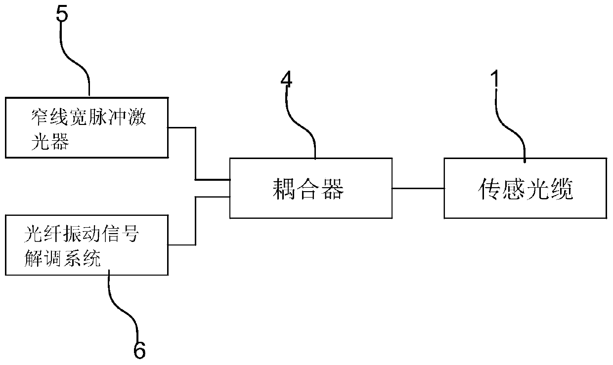
[0034] Embodiment: In this example, the optical fiber vibration signal demodulation system 6 selects the optical fiber vibration signal phase demodulation system. Several main characteristic parameters of the optical signal are light intensity, phase, polarization state, etc., and the characteristics of the optical signal will be caused when vibration occurs. When the parameters change, the optical fiber vibration signal phase demodulation system works by demodulating the phase information of the optical signal through the existing algorithm.

[0035] In actual operation, the narrow linewidth pulse laser 5, the optical fiber vibration signal phase demodulation system, and the optical cable laid on the bridge are connected through the coupler 4 according to the implementation steps of the specific implementation plan. After debugging the whole system, the light generated by the narrow-linewidth pulsed laser 5 enters the optical cable through the coupler 4. When a vehicle passes ...


PUM


Abstract

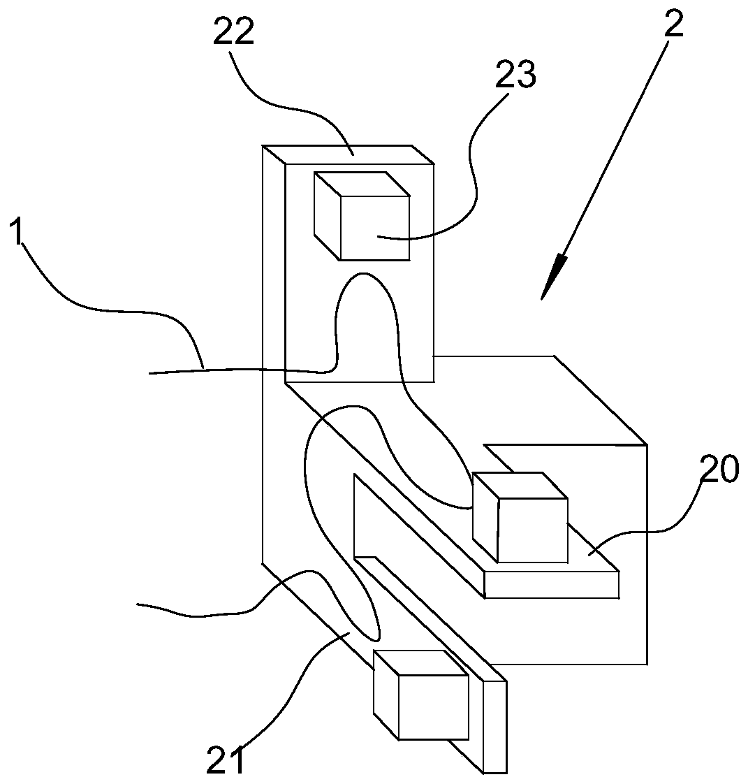
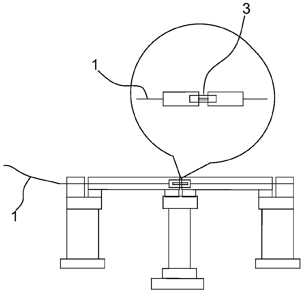
The invention discloses a bridge safety monitoring method based on an optical fiber, and a monitoring mechanism thereof. The method comprises the following steps: laying a sensing optical cable alonga bridge structure direction, arranging a three-dimensional acceleration structure on the bridge, and winding the sensing optical cable on a three-dimensional acceleration structure; arranging an optical fiber displacement sensor at a connecting part of the adjacent bridge floors, and enabling the optical fiber displacement sensor to communicate and connect with a input end of the optical fiber sensor through the sensing optical cable; communicating and connecting with a coupler at an end part of the sensing optical cable, and communicating and connecting with a narrow linewidth pulse laser device and an optical fiber vibration signal demodulation system through the coupler; enabling the emitted light to enter the sensing optical cable through the coupler by the narrow linewidth pulse laser device, and enabling the reflected light returned by the sensing optical cable to enter an optical fiber vibration signal demodulation system through a coupler, wherein the optical fiber vibration signal demodulation system demodulates vibration information of the bridge, thereby assessing the safety condition of the bridge. The monitoring method disclosed by the invention is convenient to construct, simple in operation, good in monitoring effect, high in monitoring precision, wide in applicable range, and suitable for any bridge.

Description

technical field [0001] The invention relates to the technical field of bridge monitoring, in particular to an optical fiber-based bridge safety monitoring method and a monitoring mechanism thereof. Background technique [0002] With the rapid development of my country's economy, the country's investment in infrastructure has increased year by year, and more and more bridges have been erected all over the country, and the problem of bridge safety monitoring has followed. During the service process of bridge structures, the coupling effect of disaster factors such as environmental erosion, material aging and load effects, man-made or natural mutation effects will inevitably lead to the accumulation of damage and attenuation of resistance of bridge structures, so that the resistance to natural disasters, The ability to normal load and environmental effects is reduced, causing catastrophic accidents, causing major economic losses and casualties. Therefore, effective bridge stru...

Claims


Application Information

Patent Timeline
Patent Type & Authority Applications(China)
IPC IPC(8): G01M99/00G01B11/02G01H9/00
CPCG01M99/00G01M99/004G01B11/02G01H9/004
Inventor 冉曾令肖彦波
Owner UNIV OF ELECTRONICS SCI & TECH OF CHINA
Learn More