Device and a method for determining carbon deposition rate of catalytic reforming catalyst

A catalytic reforming and catalyst technology, which is applied in the direction of measuring devices, instruments, scientific instruments, etc., can solve the problems of reducing the carbon deposition rate of catalytic reforming catalysts, cannot judge, and the carbon deposition rate of catalysts varies greatly, so as to reduce the size , reduce impact, and determine the effect of accurate results

Active Publication Date: 2019-10-18
GUANGDONG UNIV OF PETROCHEMICAL TECH
View PDF8 Cites 4 Cited by
  • Summary
  • Abstract
  • Description
  • Claims
  • Application Information

AI Technical Summary

Problems solved by technology

However, the biomass gasification and catalytic reforming equipment capable of continuously feeding biomass to produce hydrogen now has large-scale laboratory-scale gasification units and catalytic reforming units, and the data fluctuates greatly during the test pro

Method used


Image

  • Device and a method for determining carbon deposition rate of catalytic reforming catalyst
  • Device and a method for determining carbon deposition rate of catalytic reforming catalyst
  • Device and a method for determining carbon deposition rate of catalytic reforming catalyst

Examples


Embodiment 1

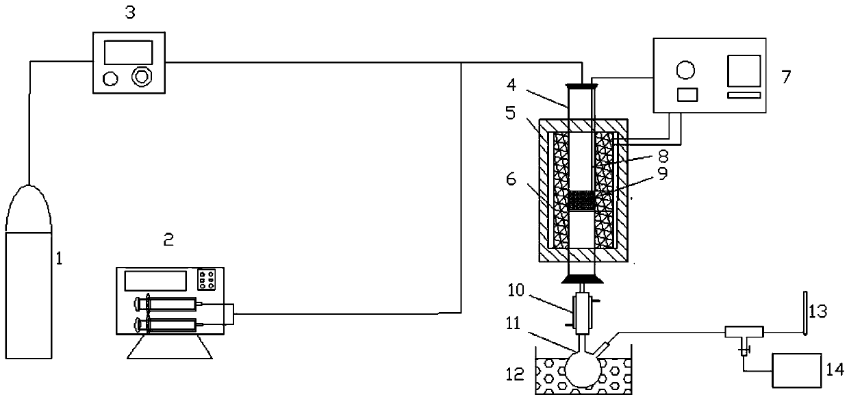
[0047] In this example, in order to study whether adding hydrogen peroxide in the reforming reactant water vapor can reduce the carbon deposition rate of the catalytic reforming catalyst during the hydrogen production process of the steam reforming of tar, a method for measuring the carbon deposition rate of the catalytic reforming catalyst is adopted. device, its structure diagram is shown in figure 1 , including: gas supply system, feed system, reaction system, product analysis system, electric heating control system;

[0048] Described gas supply system comprises nitrogen cylinder 1 and gas flowmeter 3;

[0049] The feed system includes a dual-channel micro-injection pump 2; in the dual-channel micro-injection pump 2, biomass tar is injected into the first channel, and water and hydrogen peroxide mixture are injected into the second channel; wherein, the mass of hydrogen peroxide accounts for The mass percentage of water and hydrogen peroxide mixture is 3%.

[0050] Descr...

Embodiment 2

[0079] A device for measuring the carbon deposition rate of a catalytic reforming catalyst, the same as Experimental Example 1.

[0080] A method for measuring the carbon deposition rate of a catalytic reforming catalyst, using the above-mentioned device, comprising the following steps:

[0081] (1) the catalytic reforming catalyst is loaded on the distribution net 9 in the quartz tube reactor 4;

[0082] (2) Nitrogen cylinder 1 is opened, nitrogen gas flow rate 1-10L / min is controlled by gas flowmeter 3, and the environment in quartz tube reactor 4 is purged to inert atmosphere;

[0083] (3) The electric heating temperature controller 7 is set as the reaction temperature, and the electric heating tube 6 heats the quartz tube reactor 4. After the temperature of the quartz tube reactor 4 reaches the reaction temperature, the nitrogen gas is adjusted by the gas flow meter 3 Flow 0.2-0.5L / min;

[0084] (4) After the tar and water of the double-channel micro-injection pump 2 are...


PUM


Abstract

The invention relates to a device and a method for determining the carbon deposition rate of a catalytic reforming catalyst, and belongs to the field of tar steam reforming hydrogen production. In thedevice, a nitrogen steel cylinder is communicated with the feeding port of a quartz tube reactor through a gas flowmeter; a double-channel trace injection pump is communicated with the feeding port of the quartz tube reactor; a distribution net is arranged in the middle of the quartz tube reactor, and the periphery of the quartz tube reactor is provided with a heat preservation tube; the discharge port of the quartz tube reactor is sequentially connected with a condensation tube and a liquid collector; the gas outlet of the liquid collector is connected with a soap bubble flowmeter and a gaschromatograph separately; an electric heating tube is arranged between the heat preservation tube and the quartz tube reactor; and the electric heating tube is connected with an electric heating temperature controller. By adopting the device, carbon deposition is carried out on the catalytic reforming catalyst, and the carbon deposition rate of the catalytic reforming catalyst is calculated by adopting a program heating oxidation determination and calculation; and the method is used for researching the carbon deposition rate of the steam reforming hydrogen production catalyst, the data is accurate, and the effect of the carbon deposition rate can be really reflected.

Description

technical field [0001] The invention relates to the technical field of hydrogen production by steam reforming of tar, in particular to a device and method for measuring the carbon deposition rate of a catalytic reforming catalyst. Background technique [0002] Due to the combination of renewable energy and clean energy and other environmental protection technologies, biomass gasification hydrogen production has become a very promising technology. This technology puts biomass at high temperature and undergoes pyrolysis, hydrolysis, oxidation, reduction, etc. A series of thermochemical reactions generate H 2 , CO 2 , CO, CH 4 The main product gas, after which high-purity hydrogen is produced through steam reforming, water-gas shift, separation and compression of PSA hydrogen. But in the process of pyrolysis and gasification, a by-product, tar, will inevitably be produced. It is a dark brown viscous liquid, and its main chemical composition includes two types: one is aromat...

Claims


Application Information

Patent Timeline
IPC IPC(8): G01N30/02G01N30/06
CPCG01N30/02G01N30/06
Inventor 张尤华段林海周婷孟秀红秦慧博曹水
Owner GUANGDONG UNIV OF PETROCHEMICAL TECH
Why Eureka
Try Eureka