Dust collector motor shell and dust collector motor comprising same

A technology for motor shells and vacuum cleaners, applied in the field of vacuum cleaner motor shells and vacuum cleaner motors, which can solve problems such as affecting the suction force, bursting of the outer shell, and increasing wind resistance, so as to improve processing efficiency, reduce processing costs, and reduce processing steps Effect

Pending Publication Date: 2019-10-18
地贝电机(苏州)有限公司
View PDF0 Cites 1 Cited by
  • Summary
  • Abstract
  • Description
  • Claims
  • Application Information

AI Technical Summary

Problems solved by technology

The existing vacuum cleaner motor casings have the following problems: ①Usually, when the motor is installed in the motor casing, multiple fixing procedures are required. As a result, the assembly and processing procedures of the vacuum cleaner motor and the housing are complicated; ② In order to achieve a better wind guiding effect, air guide vanes will be arranged on the cover plate. In order to reduce the overall weight and processing cost of the vacuum cleaner, the vacuum cleaner motor The casing is usually made of high-strength plastic material. However, when the vacuum cleaner has a strong suction force, it is easy to cause the outer casing to burst. Therefore, it is necessary to set a number of reinforcing ribs in the corresponding outer casing above the wind guide vane of the cover plate. , thus increasing the wind resistance, which has a great impact on the suction efficiency of the vacuum cleaner, and the cost of the outer shell of the vacuum cleaner motor is higher due to the higher price of high-strength plastics; ③ most of the outer shells of the existing vacuum cleaner motors have an integrated structure , when it is necessary to adjust the power of the motor, it is necessary to re-open the mold of the outer casing as a whole, which increases the processing cost of the vacuum cleaner motor; When the vacuum cleaner is working, the processing of the positioning opening affects the suction force at the cover plate, which has a great negative impact on the suction effect of the vacuum cleaner

Method used


Image

  • Dust collector motor shell and dust collector motor comprising same
  • Dust collector motor shell and dust collector motor comprising same
  • Dust collector motor shell and dust collector motor comprising same

Examples


Embodiment 1

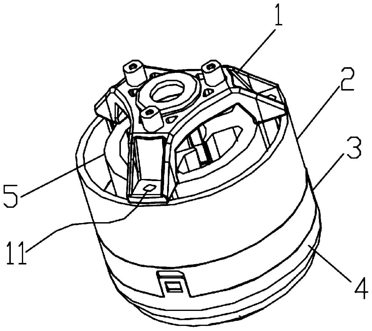
[0027] see figure 1 As shown, the motor casing of the vacuum cleaner in this embodiment includes a motor fixing frame 1, an upper casing 2, a cover plate 3 and an outer cover body 4 arranged in sequence from top to bottom, and inside the upper casing 2, it is located on the motor fixing frame 1 is provided with a motor housing frame 5 below. The upper casing 2 is snapped connected with the cover 3 , and the outer cover 4 is snapped on the side wall of the cover 3 .

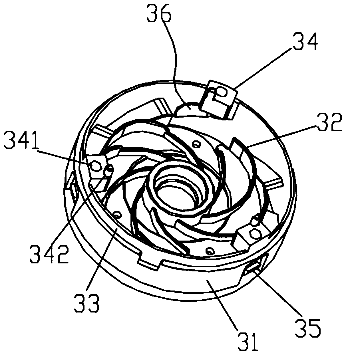
[0028] see figure 2 As shown, along the circumferential direction of the cover plate 3, a cover plate side wall 31 extending from the lower edge of the upper housing 2 is provided. The inner side of one end (i.e. the lower end in this embodiment) is provided with a number of helically distributed wind guide vanes 32, forming a spiral air guide channel in the middle of each wind guide vane 32, so that the air sucked by the motor can pass along the The air guide channel is sucked in quickly. The upper edge of t...

Embodiment 2

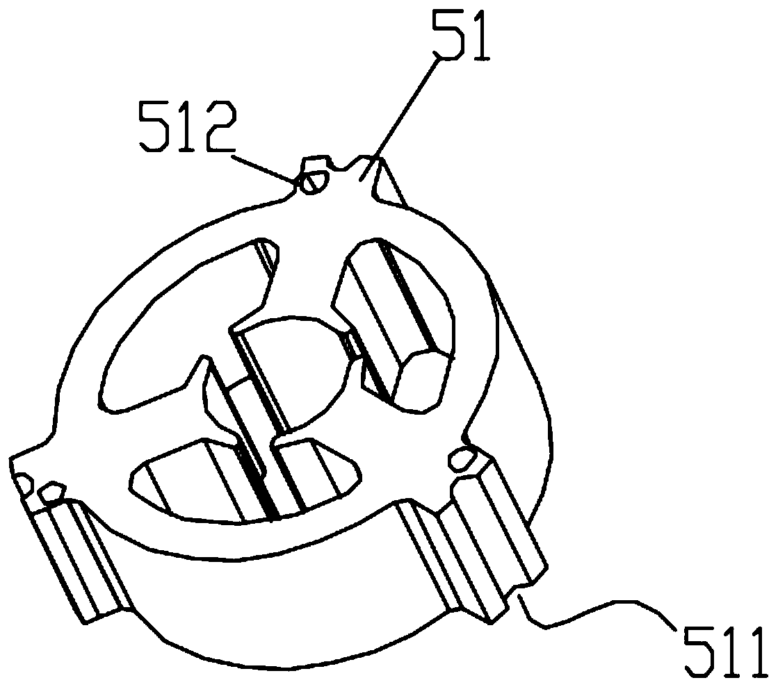
[0036] see Figure 9 As shown, the difference between this embodiment and Embodiment 1 is that the connecting ear 51 of the motor housing frame 5 is provided with a second mounting hole that communicates with the first mounting hole 341, and the second mounting hole is connected to the first mounting hole 341. It is arranged coaxially with the third mounting hole 11 and the diameters of the three holes are consistent, that is, the second mounting hole is directly opened on the connecting ear 51 , and correspondingly, there is no need to set the second slot 21 on the upper shell 2 . There is clearance fit between the outer edge of the connecting ear 51 and the upper shell 2 . The structure of the motor accommodating frame 5 in this embodiment is more convenient for processing.


PUM


Abstract

The invention discloses a dust collector motor shell. The dust collector motor shell comprises a motor fixing frame, an upper shell, a cover plate and an outer cover body which are sequentially arranged from top to bottom; a motor containing frame located below the motor fixing frame is arranged in the upper shell; and mounting holes communicated with each other are formed in the motor fixing frame, the motor containing frame and the cover plate sequentially. The dust collector motor shell further comprises a fixed impeller; the fixed impeller comprises a fixed impeller frame body and shielding sheets surrounding the fixed impeller frame body; the shielding sheets are matched with machining positioning opening in the cover plate; the fixed impeller is provided with air guide plates extending towards the motor containing frame; and the air guide plates are matched with air guide blades on the cover plate. The process of the fixation of the dust collector motor shell of the invention toa motor body can be simplified; wind resistance caused by the structure of the motor shell can be reduced; and the air suction effect of a dust collector is remarkably improved.

Description

technical field [0001] The invention relates to the technical field of vacuum cleaners, in particular to a vacuum cleaner motor housing and a vacuum cleaner motor containing it. Background technique [0002] The existing vacuum cleaner motor casing includes a cover plate and an outer casing, and the motor is arranged in the middle of the outer casing. The existing vacuum cleaner motor casings have the following problems: ①Usually, when the motor is installed in the motor casing, multiple fixing procedures are required. As a result, the assembly and processing procedures of the vacuum cleaner motor and the housing are complicated; ② In order to achieve a better wind guiding effect, air guide vanes will be arranged on the cover plate. In order to reduce the overall weight and processing cost of the vacuum cleaner, the vacuum cleaner motor The casing is usually made of high-strength plastic material. However, when the vacuum cleaner has a strong suction force, it is easy to ca...

Claims


Application Information

Patent Timeline
Patent Type & Authority Applications(China)
IPC IPC(8): H02K5/04H02K7/14A47L9/28
CPCH02K5/04H02K7/14A47L9/28
Inventor 陈海永张仁学
Owner 地贝电机(苏州)有限公司
Why Eureka
Try Eureka