Fine welding conductive nozzle and manufacturing method thereof
A contact tip and sophisticated technology, applied in the direction of electrode accessories, welding rod characteristics, etc., can solve the problems of reduced welding strength, long production cycle, complex structure, etc., and achieve the effect of increasing service life, improving conductivity, and broadening the scope of use.
- Summary
- Abstract
- Description
- Claims
- Application Information
AI Technical Summary
Problems solved by technology
Method used
Image
Examples
Embodiment 1
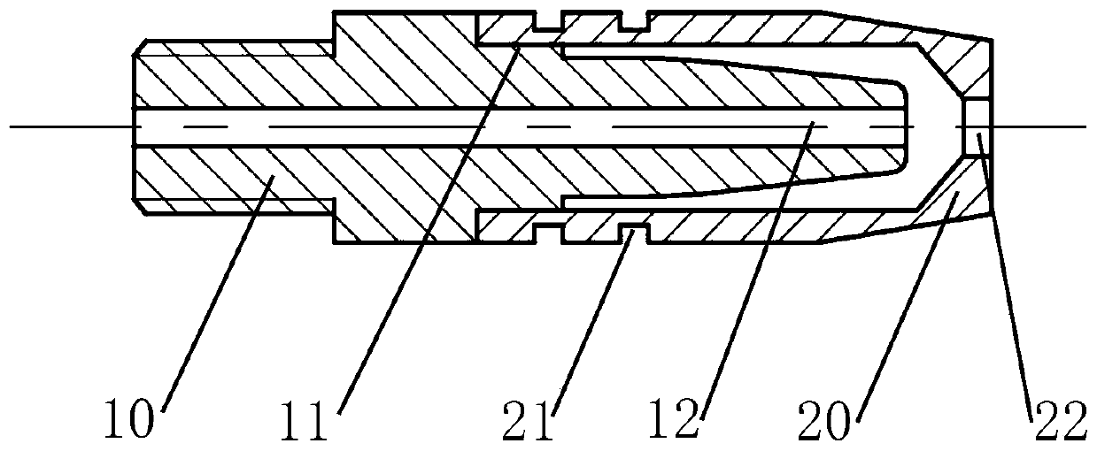
[0046] Embodiment 1: as figure 1 As shown, the contact tip is composed of a main body 10 and a heat insulating sleeve 20 . The rear end of the main body 10 is connected to the welding torch, and the connection method is determined according to the connection method with the contact tip set on the welding torch. The shape of the main body 10 is circular, oval, racetrack or polygonal. On the axis of the main body 10 is a welding wire through hole 12, the welding wire through hole 12 is an equal-diameter hole, slightly larger than the welding wire, so that the welding wire can pass through smoothly. The welding wire through hole 12 should not be too large, otherwise the performance of the contact tip to conduct electricity for the welding wire will be reduced. The penetration depth of the weld becomes shallow, and even unfused defects appear. If the aperture of the welding wire passing hole 12 is too large, it will also cause the welding wire to be inaccurate, and the current...
Embodiment 2
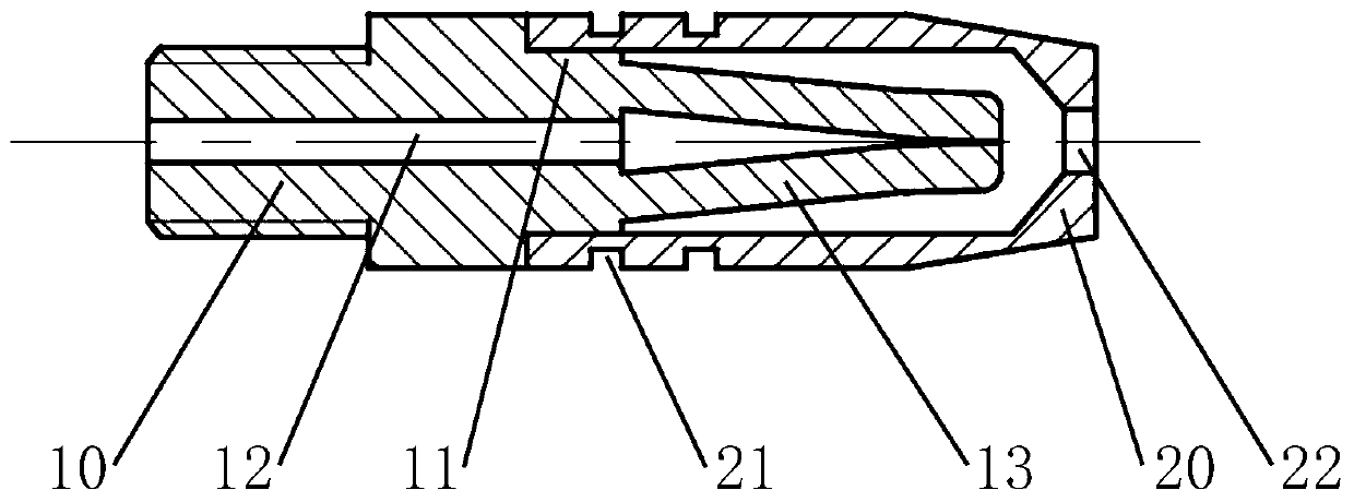
[0049] Embodiment 2: as figure 2As shown, the contact tip is composed of a main body 10 and a heat insulating sleeve 20 . The front end of the main body 10 has two conductive blocks 13 (not limited to two) that are symmetrical to the main part. The front ends of the two conductive blocks 13 are close together. The cross-sectional size and length of the block 13 remain consistent. The conductive block 13 needs to have sufficient elasticity, so the ratio of the length to the cross-sectional size should be within a reasonable range. At the same time, the conductive block 13 also needs to have an appropriate clamping force, and the conductive block 13 also needs to provide enough material for the welding wire to wear, so the cross-sectional size cannot be too small. In order to make the service life of the contact tip longer, efforts should be made to make the conductive block 13 have a longer contact surface with the welding wire. The cross-sectional size of the conductive bl...
Embodiment 3
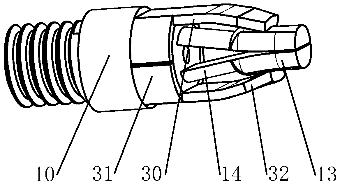
[0051] Embodiment 3: as image 3 As shown, the contact tip is composed of a main body 10 and a spring clip 30 . The rear end of the spring clip 30 is a fixed ring 31, and the cross-sectional shape of the fixed ring 31 can be circular, elliptical, racetrack-shaped and polygonal, and the specific shape is determined according to actual needs. The spring clip 30 is made of 304, 17-7PH, 15-7Mo, 30W4Cr2VA, H13, GH2132, GH2135, GH4145, GH4169, GH4090, GH5605, Inconel X-750, Inconel718, Nimonic90 and other materials with good elasticity and high softening temperature. The front end of the spring clip 30 is two elastic sheets 32 symmetrically distributed, and the elastic sheets 32 are in close contact with the conductive block 13 of the main body 10 to provide elastic force for the conductive block 13 . The conductive block 13 of the main body 10 may have the shape in Embodiment 1, that is, the overall cross-section is basically the same. However, since the spring clip 30 has a good...
PUM
 Abstract
Description
Claims
Application Information
 - R&D
- Intellectual Property
- Life Sciences
- Materials
- Tech Scout
- Unparalleled Data Quality
- Higher Quality Content
- 60% Fewer Hallucinations
Browse by: Latest US Patents, China's latest patents, Technical Efficacy Thesaurus, Application Domain, Technology Topic, Popular Technical Reports.
© 2025 PatSnap. All rights reserved.Legal|Privacy policy|Modern Slavery Act Transparency Statement|Sitemap|About US| Contact US: help@patsnap.com


