Laser processing visual matching method and system and medium

A visual matching and laser processing technology, which is applied in laser welding equipment, metal processing equipment, manufacturing tools, etc., can solve the problems of not yet collecting data, not finding descriptions or reports, etc.

Inactive Publication Date: 2019-10-22
SHANGHAI JIAO TONG UNIV
View PDF8 Cites 14 Cited by
  • Summary
  • Abstract
  • Description
  • Claims
  • Application Information

AI Technical Summary

Problems solved by technology

[0007] At present, there is no description or report of the similar technology of t

Method used


Image

  • Laser processing visual matching method and system and medium
  • Laser processing visual matching method and system and medium
  • Laser processing visual matching method and system and medium

Examples


Embodiment Construction

[0106] The present invention will be described in detail below in conjunction with specific embodiments. The following examples will help those skilled in the art to further understand the present invention, but do not limit the present invention in any form. It should be noted that those skilled in the art can make several changes and improvements without departing from the concept of the present invention. These all belong to the protection scope of the present invention.

[0107] A visual matching method for laser processing provided according to the present invention, comprising:

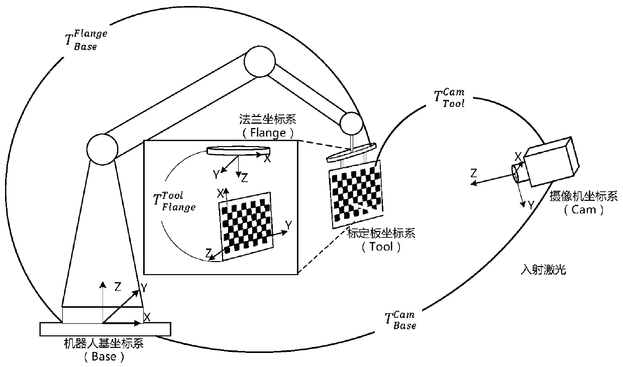
[0108] Equipment fixing steps: fix the calibration plate on the flange of the industrial robot, and place the camera at the first preset position in the outer space of the industrial robot;

[0109] Coordinate system construction steps: construct the industrial robot base coordinate system Base, the flange coordinate system Flange, the calibration plate coordinate system Tool and the camera co...


PUM


Abstract

The invention provides a laser processing visual matching method and system and a medium. The laser processing visual matching method comprises a device fixing step, wherein a calibration plate is fixed on a flange of an industrial robot, and a camera is fixedly placed at a first preset position of an external space of the industrial robot; a coordinate system construction step, wherein a base coordinate system Base, a flange coordinate system Flange, a calibration plate coordinate system Tool and a camera coordinate system Cam of the industrial robot are constructed; and a matrix acquisitionstep, wherein a closed kinematic chain equation between the four coordinate systems is established, and a homogeneous transformation matrix of the calibration plate coordinate system and the flange coordinate system is obtained. Shortcomings in the prior art are overcome, the vision-based matching method with simple operation and high precision is provided, and guarantees are provided for high-precision and high-stability operation for follow-up laser processing.

Description

technical field [0001] The invention relates to the field of laser processing, in particular to a visual matching method, system and medium for laser processing. In particular, it relates to a visual matching method for the spatial relationship between a fixed beam and an industrial robot in laser processing. Background technique [0002] The laser shot peening process uses high-energy pulsed laser-induced plasma to generate transient high-amplitude impact pressure on the metal surface, causing the material to undergo plastic deformation at a high strain rate, thereby introducing a deeper residual compressive stress than mechanical shot peening, and improving the fatigue of the metal material performance, especially suitable for strengthening the key parts of aero-engines. Compared with the traditional mechanical shot peening process, the process implementation area and shot peening parameters are precisely controllable, and the depth of residual compressive stress introduc...

Claims


Application Information

Patent Timeline
IPC IPC(8): B23K26/03B23K26/08B23K26/70G06T7/80
CPCB23K26/032B23K26/08B23K26/702G06T7/80
Inventor 胡永祥姚振强赵念友吴耀骏
Owner SHANGHAI JIAO TONG UNIV
Why Eureka
Try Eureka