Solar thermal collector and method for manufacturing solar thermal collector

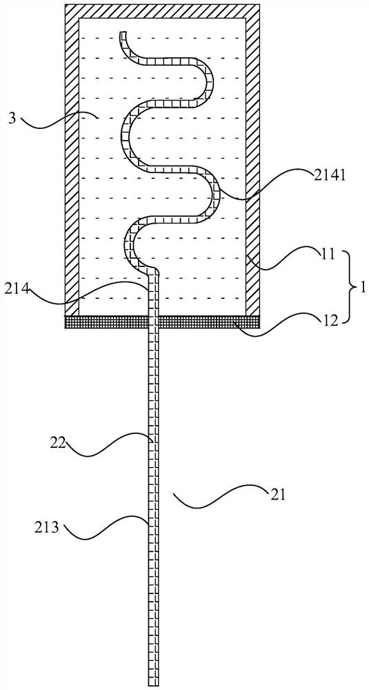
A technology of solar heat collection and manufacturing method, which is applied in the field of solar heat collection, can solve the problems of short length, small heat exchange area of ​​target medium, and low heat exchange efficiency, so as to improve service life, heat exchange efficiency, and increase heat exchange The effect of thermal area

Active Publication Date: 2021-08-10
深圳市派客新能源有限公司
View PDF7 Cites 0 Cited by
  • Summary
  • Abstract
  • Description
  • Claims
  • Application Information

AI Technical Summary

Problems solved by technology

During assembly, the head of the heat collecting tube needs to pass through the connecting piece on the heating box and enter the inside of the heat collecting box. To ensure the sealing between the heat collecting tube and the connecting piece, the heat collecting tube in the prior art extends into the heat collecting box The head of the head is a straight tube structure, and the length extending into the heat collection box is short, resulting in a small heat exchange area between the heat collection tube and the target medium in the heat collection box, and low heat exchange efficiency

Method used


Image

  • Solar thermal collector and method for manufacturing solar thermal collector
  • Solar thermal collector and method for manufacturing solar thermal collector
  • Solar thermal collector and method for manufacturing solar thermal collector

Examples


Embodiment Construction

[0033] The following will clearly and completely describe the technical solutions in the embodiments of the present invention with reference to the accompanying drawings in the embodiments of the present invention. Obviously, the described embodiments are only part of the embodiments of the present invention, not all of them. Based on the embodiments of the present invention, all other embodiments obtained by persons of ordinary skill in the art without creative efforts fall within the protection scope of the present invention.

[0034] It should be noted that all directional indications (such as up, down, left, right, front, back...) in the embodiments of the present invention are only used to explain the relationship between the components in a certain posture (as shown in the accompanying drawings). Relative positional relationship, movement conditions, etc., if the specific posture changes, the directional indication will also change accordingly.

[0035] In addition, the ...


PUM


Abstract

The invention discloses a solar heat collection device, comprising a heat collection box and a superconducting heat pipe, the heat collection box includes a box body and a sealing plate, the box body is used to hold a target medium, and the box body has an opening, The sealing plate cover is arranged on the opening; the superconducting heat pipe includes a closed tube body and a superconducting liquid poured into the tube body, and the tube body includes a connected heat collection part and a heat exchange part. The heat collecting part is located outside the box, the heat exchanging part is located inside the box, and the pipe body is embedded in the sealing plate through in-mold injection molding. The invention also discloses a method for manufacturing a solar heat collecting device, comprising the steps of: making a tube body of a superconducting heat pipe; placing the tube body in an injection mold, and injecting molding outside the tube body to form a seal by using an in-mold injection molding process; plate; pour superconducting liquid into the tube; set the sealing plate cover on the opening of a box, and make the heat collecting part of the tube outside the box and the heat exchange part of the tube inside the box inside the box.

Description

technical field [0001] The invention relates to the technical field of solar heat collection, in particular to a solar heat collection device and a manufacturing method of the solar heat collection device. Background technique [0002] With the rapid development of my country's economy, new index requirements have been put forward for the cleanliness and cost limits of energy consumption in various industries. Especially in the heating season in northern my country, smog is generated due to insufficient coal combustion and other reasons, which seriously affects air quality. . In order to reduce the consumption of coal for heating, change the habit of energy consumption, and improve the livability level, the country is gradually promoting the work of "clean energy". The medium and low temperature solar energy below 150° is playing an increasingly important role in the social energy supply system as clean energy. . [0003] The solar heat collecting device absorbs heat throug...

Claims


Application Information

Patent Timeline
Patent Type & Authority Patents(China)
IPC IPC(8): F24S10/95F24S30/40F24S70/20F24S70/60F24S80/20F24S80/70
CPCF24S10/95F24S30/40F24S70/20F24S70/60F24S80/20F24S80/70Y02E10/44Y02E10/47
Inventor 李小龙任宝平张鹏
Owner 深圳市派客新能源有限公司
Why Eureka
Try Eureka