Unequal height metal grating and manufacturing method thereof

A manufacturing method and metal grating technology, applied in the field of integrated optics, can solve the problems of the same metal grating height and single performance parameters, and achieve good optical performance, flexible adjustment, and strong focusing effect

Active Publication Date: 2019-10-22
INST OF MICROELECTRONICS CHINESE ACAD OF SCI
View PDF5 Cites 2 Cited by
  • Summary
  • Abstract
  • Description
  • Claims
  • Application Information

AI Technical Summary

Problems solved by technology

[0004] In order to overcome the problems in the prior art that the metal gratings have the same height and relatively single performance parameters, the present invention provides a method for manufacturing metal gratings with unequal heights, including:

Method used


Image

  • Unequal height metal grating and manufacturing method thereof
  • Unequal height metal grating and manufacturing method thereof
  • Unequal height metal grating and manufacturing method thereof

Examples


Embodiment 1

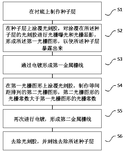
[0061] A method for manufacturing metal gratings with unequal heights, the flow chart is as follows figure 1 shown.

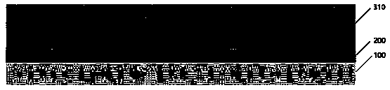
[0062] S1. Fabricate a seed layer 200 on the substrate 100 .

[0063] Such as figure 2 As shown, a 5nm Ti metal layer is first deposited on the substrate 100 by electron beam evaporation technology, and then a 10nm Au metal layer is deposited on the titanium metal layer.

[0064] S2. Coating photoresist 310 on the seed layer 200, performing grating exposure and grating development on the photoresist 310 coated on the seed layer 200, forming the first grating pattern, so that the seed Layer 200 is exposed.

[0065] Such as image 3 As shown, a layer of photoresist 310 is coated on the seed layer 200. The photoresist 310 adopts AZ6130 photoresist with a thickness of 3 microns and is exposed for 3 seconds to make the first grating pattern with 2 micron equidistant intervals, such as Figure 4 As shown, the seed layer 200 is exposed.

[0066] S3, forming the...


PUM

PropertyMeasurementUnit
Thicknessaaaaaaaaaa
Grating constantaaaaaaaaaa

Abstract

The invention discloses a manufacturing method of an unequal height metal grating. The method comprises the following steps of making a seed layer on a substrate; coating photoresist on the seed layerto make first grating patterns arranged at equal intervals; forming a first metal gate line by electroplating; coating the photoresist on the first grating patterns to make second grating patterns arranged at equal intervals, wherein a grating constant of the second grating patterns is greater than the grating constant of the first grating patterns; forming a second metal gate line through electroplating; and removing the photoresist and etching to remove the uncovered seed layer. The invention also discloses the unequal height metal grating, a two-period metal grating structure is formed, alot of optimized parameters are possessed so that adjustment is more flexible, and better optical performance is achieved.

Description

technical field [0001] The invention relates to the technical field of integrated optics, in particular to a unequal-height metal grating and a manufacturing method thereof. Background technique [0002] With the development of micro-nano processing technology, various optoelectronic devices are miniaturized and integrated, and various microstructures such as photonic crystals and gratings have been widely used in various fields, among which gratings are used in X-ray, space applications, Biomedicine, beam shaping and other fields have great application value, and various optical components made of various diffraction and polarization characteristics of gratings have become the mainstream of the market. [0003] The traditional grating is an optical writing element composed of a large number of equally spaced and parallel structures. Generally, the material of the grating is transparent glass or non-metallic material. Compared with general materials, gratings made of metal ...

Claims


Application Information

Patent Timeline
IPC IPC(8): G02B5/18G02B5/00
CPCG02B5/008G02B5/1857G02B5/1861
Inventor 张凯平
Owner INST OF MICROELECTRONICS CHINESE ACAD OF SCI
Why Eureka
Try Eureka