A method for generating a spherical milling cutter tool track for researching and matching profiles of automobile panel molds

A technology for automotive panels and spherical milling cutters, which is applied in the direction of manufacturing tools, metal processing machinery parts, metal processing equipment, etc., and can solve problems that affect the mold surface research and matching rate, complex construction methods, and errors.

Active Publication Date: 2021-01-26
HUNAN UNIV
View PDF1 Cites 0 Cited by
  • Summary
  • Abstract
  • Description
  • Claims
  • Application Information

AI Technical Summary

Problems solved by technology

The above method is aimed at the NC program that can only output the tool position point but not the tool contact point. In the solution process, it is necessary to construct an accurate mold grid model through grid mapping. The construction method is complicated, and it is easy to generate errors during the construction process. Affects the research ratio of the final mold surface

Method used


Image

  • A method for generating a spherical milling cutter tool track for researching and matching profiles of automobile panel molds
  • A method for generating a spherical milling cutter tool track for researching and matching profiles of automobile panel molds
  • A method for generating a spherical milling cutter tool track for researching and matching profiles of automobile panel molds

Examples


Embodiment Construction

[0024] When the present invention is implemented, it mainly relies on methods such as stamping simulation calculation, interpolation calculation, tool position point and tool contact offset to realize the generation of new tool tracks. Since the reconstruction methods of the research and matching profiles of the punch and die are exactly the same, here we only take the processing of any one of the research and matching profiles as an example, and the specific implementation methods are as follows:

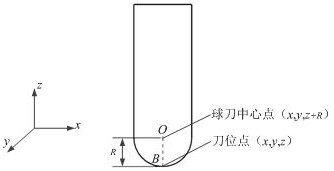
[0025] 1) Use a ball cutter to process the mold surface. At this time, the tool path is generated from the mold surface, and the corresponding tool path file is output. The file contains the tool position point and the tool contact coordinates of each tool path point. At this time The cutter position point is the center point B of the bottom of the ball cutter, and the center point O of the ball cutter is calculated by the radius offset, such as figure 1 shown.

[0026] 2) Connect...


PUM


Abstract

The invention discloses a method for manufacturing a spherical milling cutter rail of an automobile covering part mold grinding profile. The method comprises the following steps of firstly, generatinga numerical control machining cutter rail on a design model, and acquiring coordinates of a cutter center point and a cutter contact point through a cutter rail file; then, acquiring the thickness distribution of a formed part and the thickness value of each node through stamping simulation calculation, and calculating an intersection point of a connection line between the cutter center point andthe cutter contact point and a grid model of the formed part; and finally, calculating the thickness of the intersection point according to the coordinate of each node and the thickness value interpolation value of an unit in which the intersection point is located, and moving the cutter center point and the cutter contact point to form a novel numerical control machining cutter rail. According to the method, the grinding rate of a mold profile can be effectively improved, the mold manufacturing efficiency can be improved, and the mold manufacturing cost can be reduced.

Description

technical field [0001] The invention relates to the field of surface processing of researched and matched profiles of automobile cover parts, in particular to a method for generating a spherical milling cutter track for developing and matching profiles of molds of automobile cover parts. [0002] technical background [0003] During the drawing forming process, the sheet material will be thinned or thickened due to plastic deformation, and this thickness change is not uniformly distributed in each area of ​​the formed part. In order to improve the forming quality and reduce the local stress of the mold surface during stamping, it is necessary to repeatedly correct the mold surface according to the actual thickness change of the drawn formed part until the mold surface can be completely matched with the formed surface of the part when the mold is closed. Fitting, this kind of bonding degree is called "grinding rate" or "grinding ratio" in the drawing forming process, and gener...

Claims


Application Information

Patent Timeline
Patent Type & Authority Patents(China)
IPC IPC(8): B23Q15/013
CPCB23Q15/013
Inventor 龚志辉
Owner HUNAN UNIV
Why Eureka
Try Eureka