Production mold and production process of special-shaped prefabricated heat insulating pipe member

A pipe fitting and special-shaped technology, which is applied in the production mold and production process field of special-shaped prefabricated thermal insulation pipe fittings, can solve the problems of low production efficiency, numerous steps, and time-consuming, etc., and achieve the effects of improved production process efficiency, simple operation and reliable effect

Pending Publication Date: 2019-11-01
HENAN SANJIE THERMOELECTRIC TECH
View PDF14 Cites 1 Cited by
  • Summary
  • Abstract
  • Description
  • Claims
  • Application Information

AI Technical Summary

Problems solved by technology

[0002] At present, the domestic manufacturing of prefabricated direct-buried thermal insulation pipe fittings basically adopts the pipe-in-pipe technology, in which plastic brackets, wood blocks and other materials are used as supporting concentric technical means between the outer protective pipe and the working pipe (usually steel pipe), and then outside The protective pipe and working pipe parts are injected with polyurethane for foaming; when producing prefabricated insulating elbows or tees and other special-shaped prefabricated insulating pipe fittings, in order to make the shape of the outer protective pipe conform to the shape of the inner pipe, the current conventional practice is Cut the polyethylene outer protective pipe according to the preset shape, and then splice the cut polyethylene outer protective pipe on the outside of the steel pipe according to the radian, and then fix and seal the joints, and finally install the special-shaped prefabricated thermal insulation pipe fittings The two ends of the special-shaped prefabricated thermal insulation pipe are sealed, and then polyurethane foam is injected into the special-shaped prefabricated thermal insulation pipe from one or both ends. Finally, the polyurethane foam is fixed and formed, and the sealing devices at both ends of the special-shaped prefabricated thermal insulation pipe are removed and both ends are leveled. That is to say, the production of the entire special-shaped prefabricated thermal insulation pipe fittings is completed; it can be seen from the above steps that the entire production process of special-shaped prefabricated thermal insulation pipe fittings still needs consumables such as brackets, and the steps of bundling and supporting are numerous, time-consuming, and production efficiency is not high.

Method used


Image

  • Production mold and production process of special-shaped prefabricated heat insulating pipe member
  • Production mold and production process of special-shaped prefabricated heat insulating pipe member
  • Production mold and production process of special-shaped prefabricated heat insulating pipe member

Examples


Embodiment 1

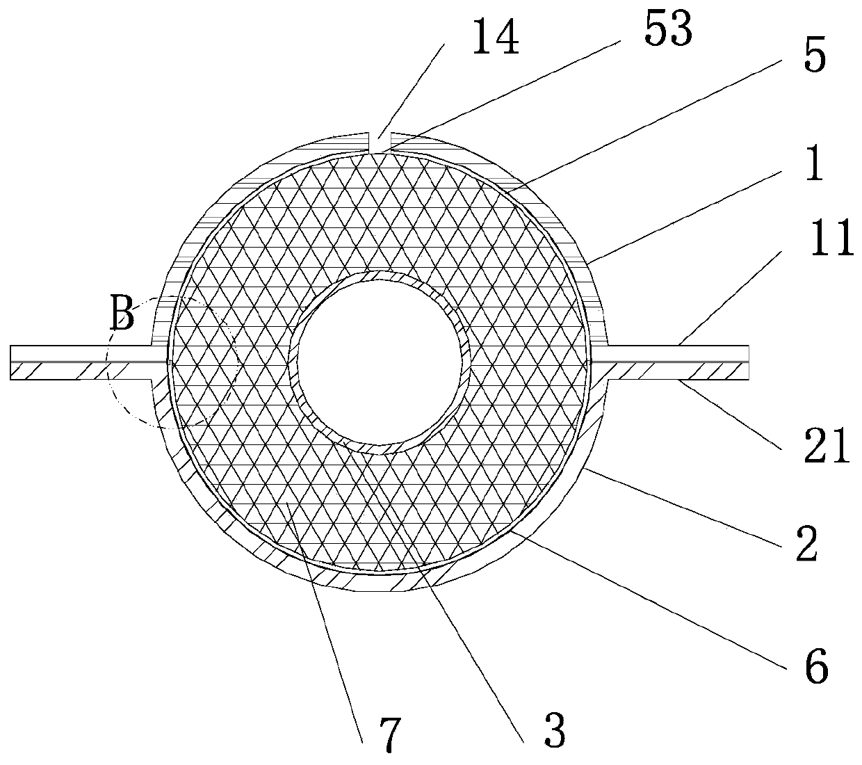
[0037] The inner pipe 3 in the drawings of the description of the present invention is the working pipeline in the center of the special-shaped prefabricated thermal insulation pipe fittings, usually a steel pipe, which is the prior art, and the foam layer 7 in the drawings of the description of the present invention is formed by polyurethane foaming of the prefabricated thermal insulation pipe fittings The polyurethane insulation layer is prior art.

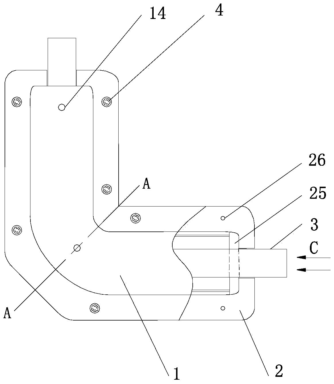
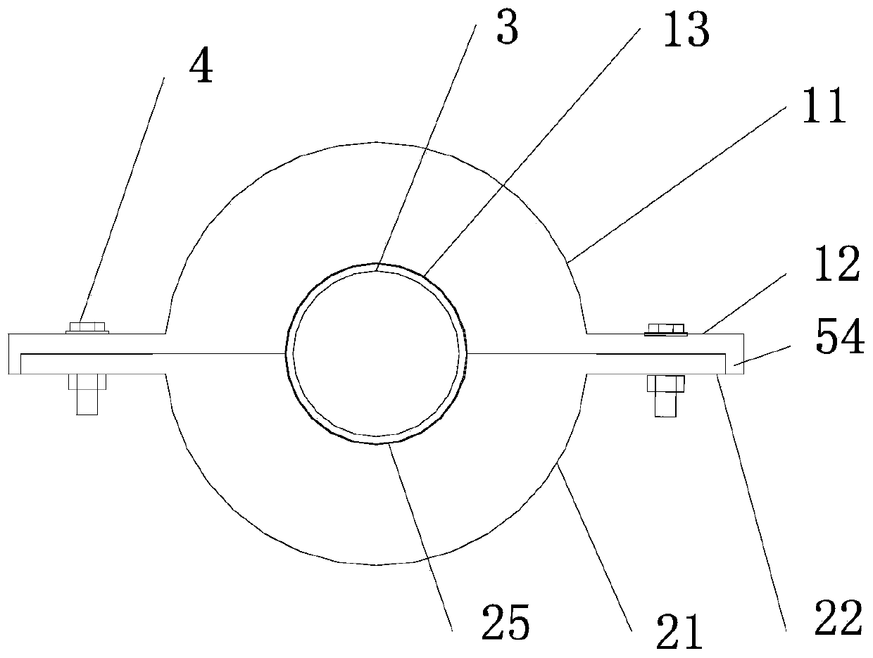
[0038] Such as Figure 1 to Figure 4 As shown, a production mold of a special-shaped prefabricated thermal insulation pipe fitting includes an upper mold 1, a lower mold 2 and an outer protective pipe;

[0039] The lower part of the upper mold 1 is provided with an upper foaming chamber, the upper part of the lower mold 2 is provided with a lower foaming chamber, the two ends of the upper foaming chamber are provided with an upper side plate, and the center of the lower part of the upper side plate is provided with an upper semi...

Embodiment 2

[0057] This embodiment is another implementation based on the embodiment 1, the description of the same technical solutions as the embodiment 1 will be omitted, and only the technical solutions different from the embodiment 1 will be described. In Embodiment 2, an "I"-shaped connector 8 is used to connect the upper protective shell 5 and the lower protective shell 6 .

[0058] Such as Figure 4 , Figure 5 As shown, the upper protective shell 5 and the lower protective shell 6 are connected by an "I"-shaped connecting piece 8, the connecting piece 8 is made of flexible material, specifically polyethylene material, and the upper part of the connecting piece 8 is formed to accommodate the upper protective shell 5 The upper insertion space 84 of the lower edge, the lower part of the connecting piece 8 forms the lower insertion space for accommodating the upper edge of the lower protective shell 6; the connecting piece 8 can be directly produced into strips according to the speci...


PUM

PropertyMeasurementUnit
thicknessaaaaaaaaaa

Abstract

The invention relates to a production mold of a special-shaped prefabricated heat insulating pipe member. The production mold comprises an upper mold, a lower mold and an outer protective pipe; an upper foaming cavity is formed in the lower portion of the upper mold, a lower foaming cavity is formed in the upper portion of the lower mold, upper side plates are arranged at the two ends of the upperfoaming cavity, upper semicircular holes are formed in the centers of the lower positions of the upper side plates, lower side plates are arranged at the two ends of the lower foaming cavity, and lower semicircular holes are formed in the centers of the lower positions of the lower portions of the lower side plates; and a foaming mold cavity with a round cross section is formed by the upper foaming cavity and the lower foaming cavity when the upper mold and the lower mold are closed, inner pipe perforation holes with round cross sections are formed by the upper semicircular holes and the lower semicircular holes, and the foaming mold cavity and the inner pipe perforation holes are concentric; and the outer protective pipe comprises an upper protective shell and a lower protective shell which are buckled into a barrel. By means of the production mold, the density of a polyurethane layer can be improved, the production efficiency of the special-shaped prefabricated heat insulating pipeis improved, and the production mold is easy to learn and easy to use.

Description

technical field [0001] The invention belongs to the technical field of production of prefabricated thermal insulation pipe fittings, and in particular relates to a production mold and a production process of special-shaped prefabricated thermal insulation pipe fittings. Background technique [0002] At present, the domestic manufacturing of prefabricated direct-buried thermal insulation pipe fittings basically adopts the pipe-in-pipe technology, in which plastic brackets, wood blocks and other materials are used as supporting concentric technical means between the outer protective pipe and the working pipe (usually steel pipe), and then outside The protective pipe and working pipe parts are injected with polyurethane for foaming; when producing prefabricated insulating elbows or tees and other special-shaped prefabricated insulating pipe fittings, in order to make the shape of the outer protective pipe conform to the shape of the inner pipe, the current conventional practice ...

Claims


Application Information

Patent Timeline
Patent Type & Authority Applications(China)
IPC IPC(8): B29C44/14B29C44/58B29L23/00
CPCB29C44/143B29C44/58B29L2023/22
Inventor 陈朋张向辉张娇
Owner HENAN SANJIE THERMOELECTRIC TECH
Why Eureka
Try Eureka