Construction method of reinforced concrete liner composite lining structural form of shield tunnel

A reinforced concrete and composite lining technology, which is applied in the field of infrastructure engineering, can solve the problems of affecting water flow conditions, complex process, high cost, etc., and achieve the effects of improving bending stiffness, clear structure type, and high economic benefits

Inactive Publication Date: 2019-11-01
GUANGDONG RES INST OF WATER RESOURCES & HYDROPOWER
6 Cites 0 Cited by

AI-Extracted Technical Summary

Problems solved by technology

[0003] Among them, although the lining type of shield lining + steel pipe lining (concrete filling inside) can withstand high internal water pressure, there are several problems: 1) steel pipes need to be welded in the tunnel and construction is inconvenient; 2) due to the hardening of concrete The volume shrinks, and the filling layer is difficult to fill; 3) The inner lining ...

Method used

In sum, reinforcing bar is implanted into the shield segment, and the exposed part of the reinforcing bar is welded or bound together with the lining steel cage, and then pouring the concrete lining, so that the reinforced concrete lining is connected with the outer lining shield tunnel together to form a composite structure. The advantages of this new structure are: 1) Both can withstand the internal water pressure and external water and soil pressure; 2) The bending stiffne...

Abstract

The invention discloses a construction method of a reinforced concrete liner composite lining structural form of a shield tunnel. Outer liner shield segments and inner liner reinforced concrete segments are connected together through shear bonds to be subjected to joint stress, so that flexural rigidity of a lining structure can be improved, and internal water pressure borne by the lining is increased; the structural form is clear and convenient to construct and has higher economic benefits, one effective and practical structural form can be provided for a large-diameter water transfer tunnel,especially a water transfer tunnel with high internal water pressure, and the structural form can be widely applied to the technical field of construction work.

Application Domain

Underground chambersTunnel lining +1

Technology Topic

RebarWater transfer +9

Image

  • Construction method of reinforced concrete liner composite lining structural form of shield tunnel
  • Construction method of reinforced concrete liner composite lining structural form of shield tunnel
  • Construction method of reinforced concrete liner composite lining structural form of shield tunnel

Examples

  • Experimental program(1)

Example Embodiment

[0034] The present invention will be further explained and illustrated below in conjunction with the drawings and specific embodiments of the specification.
[0035] The embodiment of the present invention provides a method for constructing a reinforced concrete lining composite lining structure of a shield tunnel, which includes the following steps:
[0036] Reinforcement treatment on the shield tunnel segments, or reserve connecting steel bars in the shield tunnel segments;
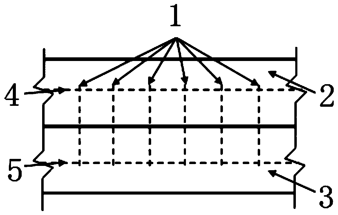
[0037] Bind or weld the connecting steel bar and the steel bar cage lined with reinforced concrete to form a shear key;
[0038] Support the steel cage and pour concrete to form a reinforced concrete lining;
[0039] The shield-concrete lining composite structure is constructed by shearing keys.
[0040] Further as a preferred embodiment, it also includes the following steps:
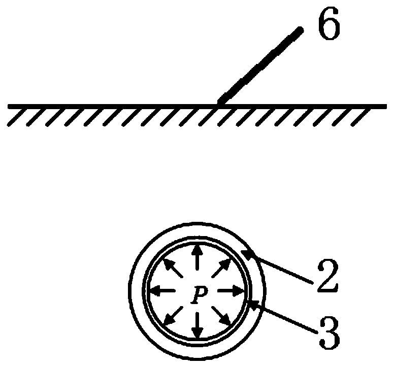
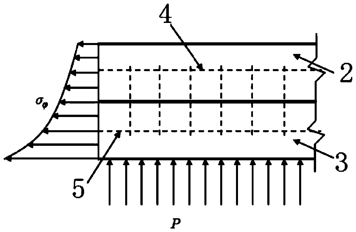
[0041] The shear key bears the internal water pressure and external water and soil pressure of the shield-concrete lining composite structure.
[0042] Further as a preferred embodiment, it also includes the following steps:
[0043] The cross-section height of the shield-concrete-lined composite structure is increased through the shear key.
[0044] As a further preferred embodiment, the deformation of the outer lining shield tube segment is restricted by shear keys.
[0045] Further as a preferred embodiment, the step of bearing the internal water pressure and external water and soil pressure of the shield-concrete lining composite structure through the shear key includes the following steps:
[0046] Calculate the displacement of the thick-walled cylindrical structure according to the Lame formula;
[0047] According to the calculated displacement of the thick-walled cylindrical structure, the radial deformation results of the inner reinforced concrete lining and the outer lining shield segment are determined.
[0048] As a further preferred embodiment, the step of increasing the cross-sectional height of the shield-concrete-lined composite structure through the shear key includes the following steps:
[0049] Calculate the flexural rigidity of the composite structure according to the stress characteristics of the shield-concrete lining composite structure;
[0050] According to the calculated flexural rigidity, the effect of shearing key on the section height of the shield-concrete lining composite structure is determined.
[0051] Further as a preferred embodiment, the step of restricting the deformation of the outer lining shield segment through the shear key includes the following steps:
[0052] Calculate the hoop stress of thick-walled cylindrical structure;
[0053] According to the calculated hoop stress, the deformation result of the outer lining shield segment is determined.
[0054] The following describes the shield tunnel reinforced concrete lining composite lining structure type of the present invention in detail with reference to the accompanying drawings:
[0055] Such as figure 1 Shown, where, attached Figure 1-3 The meanings of the marks in are as follows: 1 stands for connecting steel bars; 2 stands for shield tunnel segments; 3 stands for reinforced concrete lining; 4 stands for shield steel bars; 5 stands for lining steel bars; 6 stands for surrounding rock; Stands for hoop stress; P stands for internal water pressure.
[0056] The method for constructing the reinforced concrete lining composite lining structure of the shield tunnel of the present invention is:
[0057] S1. Reinforce the shield tunnel segment 2 or reserve the connection rebar position;
[0058] S2 Binding or welding the connecting steel bar 1 and the steel bar cage lined with reinforced concrete 3 to form a shear key;
[0059] S3. Support formwork and pour concrete to form a reinforced concrete lining 3;
[0060] S4. Utilize the connection effect (shear key) of the connecting steel bar 1 to form a shield-concrete lining composite structure under common force.
[0061] The advantages of the structure of the present invention are:
[0062] (1) Through the function of the shear key, the shield-concrete lining composite structure can jointly bear the internal water pressure and the external water and soil pressure, and ensure the coordination of radial deformation;
[0063] Specifically, see the elastic mechanics model of shield tunnel structure figure 2 As shown, according to the Lame solution of the plane strain axisymmetric problem, the calculation formula for the displacement of the thick-walled cylindrical structure is:
[0064]
[0065] Where: Δr is the elongation of the circle radius, μ is the Poisson's ratio, E is the material's elastic modulus, r and R are the inner and outer diameters of the circle, ρ is the radius at the calculated position, and p is the internal water pressure.
[0066] According to the calculation results, the ρ at the interface between the inner lining reinforced concrete and the outer shield tunnel segment is consistent, so the deformation of the two is coordinated under load.
[0067] (2) The bending height of the cross-section after the composite structure is greater than the bending height before the composite, so the flexural stiffness W2 after composite is greater than the flexural stiffness before composite W1, which increases the flexural rigidity of the cross-section;
[0068] Wherein, the calculation formula for the bending stiffness of the section is:
[0069]
[0070]
[0071]
[0072] In the formula: W is the bending stiffness, I z Is the moment of inertia of the section, y is the farthest distance from the neutral axis on the section, b is the width of the section, h 1 ,h 2 It is the thickness of the shield segment and the lining reinforced concrete.
[0073] According to the calculation formula, the bending rigidity of the structure is proportional to the square of the thickness, so the bending rigidity of the new composite structure is greater than that of the original structure, and the new structure can increase the bending resistance of the section.
[0074] (3) In view of the effect of the shear key formed by the connecting steel bars, even if the reinforced concrete lining cracks and the internal water seeps out, the shear key can limit the mirror image deformation of the outer lining shield segment, thereby increasing the resistance of the outer lining shield segment. Safety guarantee under high internal water pressure.
[0075] Circumferential stress of thick-walled cylindrical structure (see image 3 Shown), as:
[0076]
[0077] Where: Is the circumferential stress of the section, A and C are constants determined by the boundary conditions and constraints, and ρ is the radius at the calculated position.
[0078] From the inside to the outside, the hoop stress becomes smaller and smaller and presents a hyperbolic shape. When the internal water pressure is small, the reinforced concrete lining does not crack, and the planting bars only play the role of the composite shield segment and reinforced concrete; The internal water pressure increases and the reinforced concrete lining cracks. In the most unfavorable situation, all internal water pressure directly acts on the segment, causing the segment to expand radially. At this time, the shear key formed by the connecting steel bar will limit the deformation of the segment. Increased the safety reserve of shield segments.
[0079] In the following, the new structure of the present invention will be explained with a concrete lining stiffness reduction calculation case. The connection between the shield segment and the lining concrete is not considered in the calculation, so as to view the deformation and force of the lining reinforced concrete under internal water pressure. On this basis, the connecting steel bars are used as safety reserves, which can better ensure the safety of the composite structure.
[0080] Before cracking, the elastic modulus of the reinforced concrete lining is 30 GPa. As the internal water pressure increases, the reinforced concrete gradually cracks, and the rigidity of the reinforced concrete lining gradually decreases. Due to the action of the lining steel bars, the rigidity of the reinforced concrete will not decrease to 0 . Calculate the relationship between the lining stress and the internal water pressure when the stiffness of the lining reinforced concrete is reduced to 1/2, 1/3, 1/5, 1/10, 1/15. The surrounding rock considers 2GPa and 3GPa. See the calculation results Figure 4 , Figure 5 , Image 6 , Figure 7 Shown.
[0081] It can be seen from the calculation results that as the stiffness of the cracked concrete decreases, the radial displacement of the lining will gradually increase and the stress of the lining will gradually decrease. However, due to the traction of the lining steel bars (shear keys), the reinforced concrete lining remains Retain a certain strength. At this time, the connecting steel bars can better connect the inner lining and the shield segment as a whole to enhance the strength and safety of the composite structure.
[0082] To sum up, the steel bars are implanted into the shield tunnel segments, and the exposed part of the steel bars is welded or tied together with the lining steel cage, and then the concrete lining is poured to connect the reinforced concrete lining and the outer lining shield tunnel together. Form a composite structure. The advantages of this new structure are: 1) the two can bear the internal water pressure and external water and soil pressure together; 2) increase the flexural rigidity of the structure; 3) in view of the connection of steel bars, even if the reinforced concrete lining cracks, internal water seepage , It can also ensure the safety of the outer lining shield segment under the action of high internal water pressure. The invention has a clear structure type, convenient construction and high economic benefits, and can provide an effective and feasible structure type for high internal water pressure water conveyance tunnels.
[0083] The above is a detailed description of the preferred implementation of the present invention, but the present invention is not limited to the described embodiments. Those skilled in the art can make various equivalent modifications or substitutions without departing from the spirit of the present invention. These equivalent modifications or replacements are all included in the scope defined by the claims of this application.

PUM

no PUM

Description & Claims & Application Information

We can also present the details of the Description, Claims and Application information to help users get a comprehensive understanding of the technical details of the patent, such as background art, summary of invention, brief description of drawings, description of embodiments, and other original content. On the other hand, users can also determine the specific scope of protection of the technology through the list of claims; as well as understand the changes in the life cycle of the technology with the presentation of the patent timeline. Login to view more.

Similar technology patents

Attachment layer reinforced grid ribbed cylindrical shell structure

InactiveCN106197171AIncreased bending stiffness
Owner:DALIAN UNIV OF TECH

Hollow interlayer heat-insulating wall board and processing and manufacturing method thereof

ActiveCN103321309AIncreased bending stiffnessSimple and efficient operation
Owner:河北北方绿野居住环境发展有限公司

Beam type regenerative buffer guardrail

PendingCN114508060AIncreased bending stiffnessreduce distortion
Owner:CHINA CONSTR THIRD ENG BUREAU GRP CO LTD

Lightweight FRP water conveying pipe and processing technology thereof

PendingCN114838211AIncreased bending stiffnessreduce damage
Owner:NANJING UNIV OF TECH +1

Engineering machinery cover and engineering machinery

InactiveCN103572793AIncreased bending stiffnessImprove opening efficiency
Owner:CATEPILLAR SARL

Classification and recommendation of technical efficacy words

  • clear structure
  • Increased bending stiffness

Multi-level progressive classification and identification method for small-current ground faults

ActiveCN108008244AAvoid conceptual ambiguityclear structure
Owner:STATE GRID HUBEI ELECTRIC POWER RES INST +2

Preparation method for linear polycarboxylate type water reducing agent special for semi-hydrated gypsum

ActiveCN103664043Aclear structureExcellent water reduction and retarding effect
Owner:CHINA UNIV OF MINING & TECH (BEIJING)

Fluorine-cation-containing WPU (waterborne polyurethane) and preparation method thereof

ActiveCN103044649Aclear structureRaw material controllable
Owner:无锡智慧兴宜信息技术有限公司

Device for detachably coupling two parts

InactiveCN101262969AIncreased bending stiffness
Owner:KOMET GROUP GMBH

Hollow interlayer heat-insulating wall board and processing and manufacturing method thereof

ActiveCN103321309AIncreased bending stiffnessSimple and efficient operation
Owner:河北北方绿野居住环境发展有限公司

Attachment layer reinforced grid ribbed cylindrical shell structure

InactiveCN106197171AIncreased bending stiffness
Owner:DALIAN UNIV OF TECH

Lightweight FRP water conveying pipe and processing technology thereof

PendingCN114838211AIncreased bending stiffnessreduce damage
Owner:NANJING UNIV OF TECH +1

Engineering machinery cover and engineering machinery

InactiveCN103572793AIncreased bending stiffnessImprove opening efficiency
Owner:CATEPILLAR SARL
Why Eureka
Try Eureka