Fixed-point rotary cutting method for off-axis microlens machining
A fixed-point rotation and cutting method technology, which is applied in the field of ultra-precision machining of microlens optical elements, can solve problems such as unfavorable X-axis smooth movement, difficulty in cutting trajectory planning, and reduced machining accuracy of off-axis microlenses, so as to increase stability and improve The effect of machining accuracy
- Summary
- Abstract
- Description
- Claims
- Application Information
AI Technical Summary
Problems solved by technology
Method used
Image
Examples
specific Embodiment approach 1
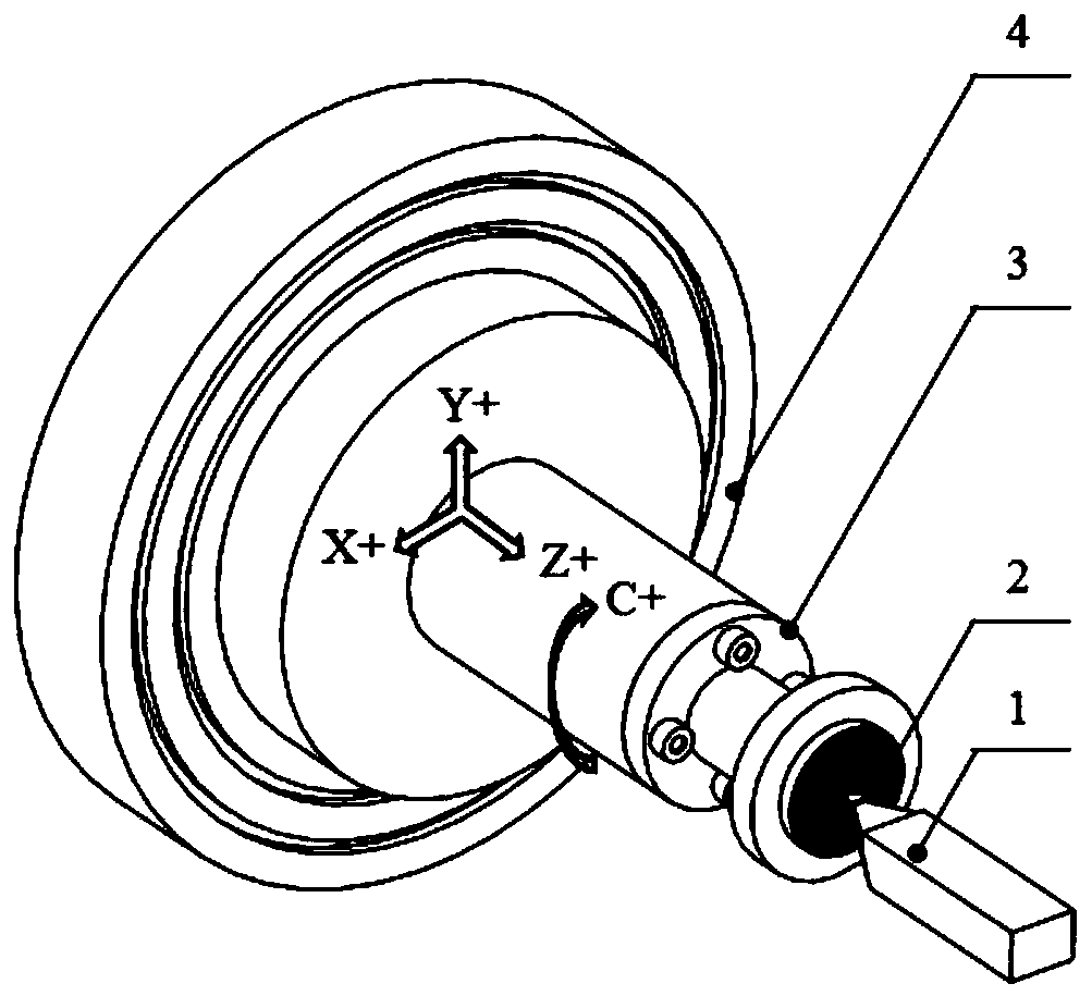
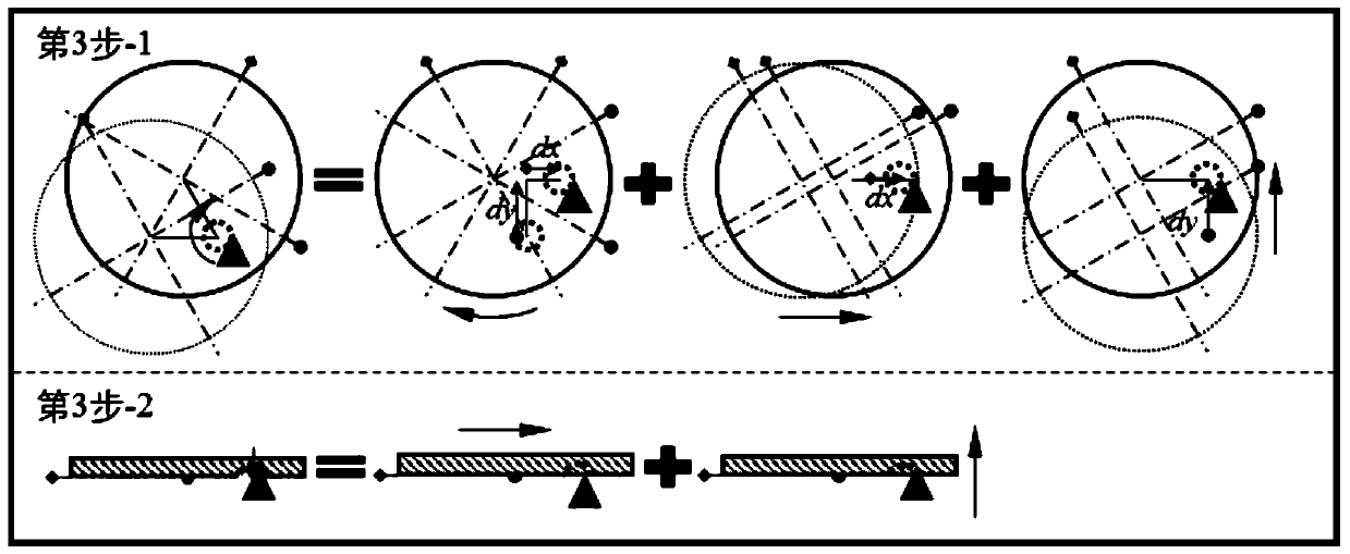
[0040] Specific implementation mode one: combine Figure 1 to Figure 4 Describe this embodiment mode, a kind of fixed-point rotary cutting method for off-axis microlens processing of this embodiment mode, it comprises the following steps:
[0041] Step 1: Adjust the distance between the workpiece rotation center axis and the spindle axis of the ultra-precision machine tool, so that the radial distance between the two axes is controlled within 0.5 μm (inclusive); the workpiece 2 is glued to the fixture 3, and the fixture 3 is vacuum-adsorbed to the ultra-precision machine tool The vacuum chuck 4; use the precision measuring tools such as inductance micrometer or dial indicator that comes with the machine tool to measure the radial circular runout error of the cylindrical surface of the workpiece 2, and adjust the fixture 3 by tapping the leather hammer along the radial direction so that the workpiece 2 is rotating The radial circular runout error within one week is controlled w...
specific Embodiment approach 2
[0055] Specific implementation mode two: combination Figure 1 to Figure 4 This embodiment is described. The fixed-point rotary cutting method of this embodiment is suitable for processing various types of materials. For example, in step one, the material of the processed part can be a plastic material used as a mold, such as duralumin 6061, die steel, electroless nickel, etc., or a brittle material as a separate part product, such as a single Crystal germanium, single crystal silicon, etc. Such setting makes the processing method have a wider scope of material application. Other compositions and connections are the same as in the first embodiment.
[0056] In step 1 of this embodiment, the material of the processed part is a plastic material or a brittle material; the type of the microlens unit of the processed part is a concave mirror or a convex mirror.
specific Embodiment approach 3
[0057] Specific implementation mode three: combination Figure 1 to Figure 4 This embodiment will be described. In this embodiment, a variety of processing tools with different shapes and materials can be selected. For example, in step 2, the tool material used can be either single crystal diamond, nano-twinned diamond, or polycrystalline diamond and other tool materials used for ultra-precision machining of optical elements. The shape of the tool used can be either a formed turning tool or a non-shaped turning tool, for example, a circular arc edge turning tool, a straight edge turning tool and a sharp knife. If the tool used is an arc-edge turning tool, the arc radius of the tool tip is not greater than the minimum radius of curvature of the generatrix of the microlens profile. Such setting makes the processing method have more flexible tool parameter setting and expands the applicable range of the method. Other compositions and connections are the same as those in Embodim...
PUM
| Property | Measurement | Unit |
|---|---|---|
| diameter | aaaaa | aaaaa |
| diameter | aaaaa | aaaaa |
Abstract
Description
Claims
Application Information
 - R&D
- Intellectual Property
- Life Sciences
- Materials
- Tech Scout
- Unparalleled Data Quality
- Higher Quality Content
- 60% Fewer Hallucinations
Browse by: Latest US Patents, China's latest patents, Technical Efficacy Thesaurus, Application Domain, Technology Topic, Popular Technical Reports.
© 2025 PatSnap. All rights reserved.Legal|Privacy policy|Modern Slavery Act Transparency Statement|Sitemap|About US| Contact US: help@patsnap.com


