A fixed-point rotary cutting method for off-axis microlens processing

A technology of fixed-point rotation and cutting method, which is applied in the field of ultra-precision machining of microlens optical elements, which can solve the problems of difficult planning of cutting trajectory, reduction of off-axis microlens machining accuracy, unfavorable X-axis smooth movement, etc.

Active Publication Date: 2020-07-07
HARBIN INST OF TECH
View PDF5 Cites 0 Cited by
  • Summary
  • Abstract
  • Description
  • Claims
  • Application Information

AI Technical Summary

Problems solved by technology

[0005] The purpose of the present invention is to solve the existing slow tool servo method or fast tool servo method because the high-frequency compensation motion is added on the X-axis and Z-axis of the machine tool, which is not conducive to the smooth movement of the X-axis with large inertia, resulting in reduced off-axis The problem of the machining accuracy of the microlens and the difficulty of planning the cutting trajectory

Method used


Image

  • A fixed-point rotary cutting method for off-axis microlens processing
  • A fixed-point rotary cutting method for off-axis microlens processing
  • A fixed-point rotary cutting method for off-axis microlens processing

Examples


specific Embodiment approach 1

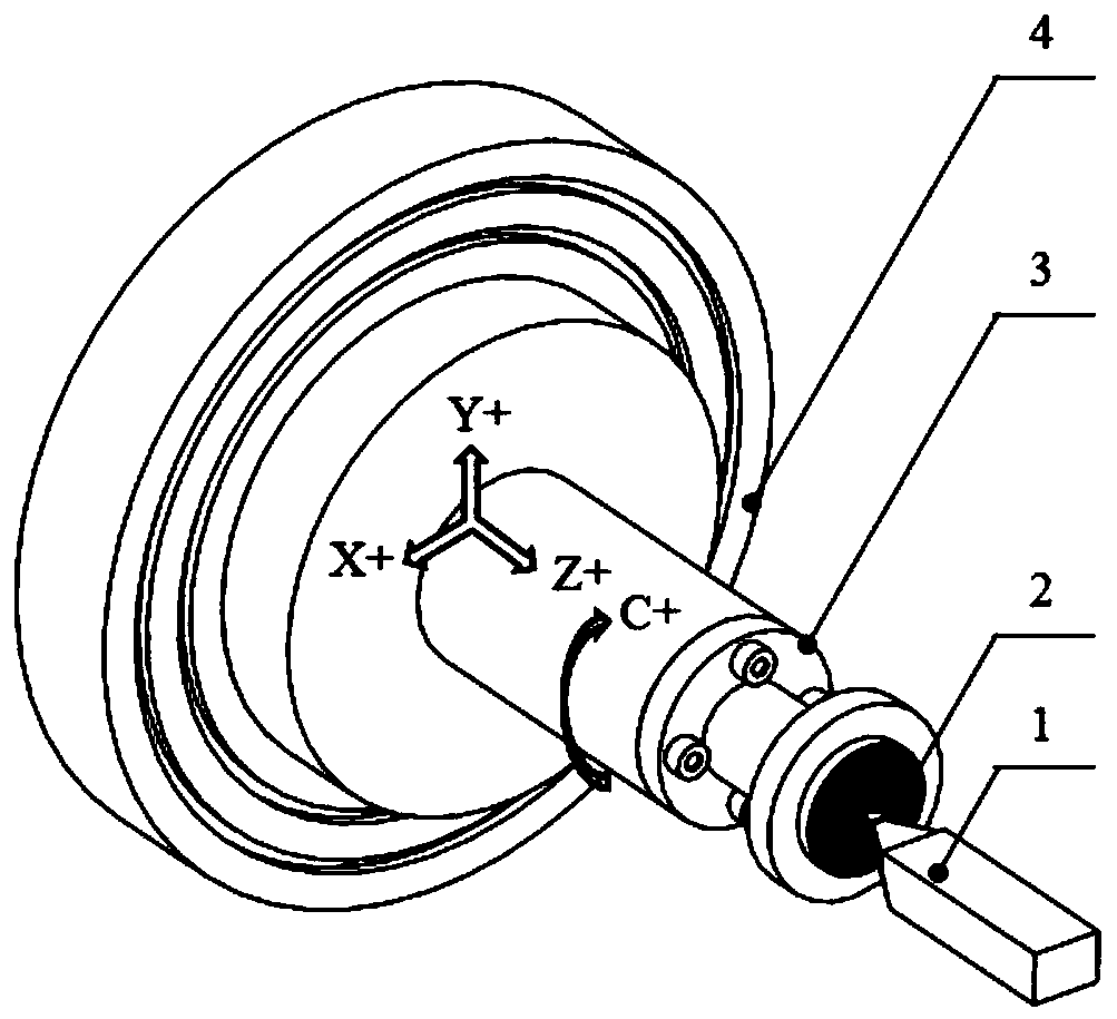
[0040] Specific implementation mode 1: Combination Figure 1 to Figure 4 To describe this embodiment, a fixed-point rotary cutting method for off-axis microlens processing in this embodiment includes the following steps:

[0041] Step 1: Adjust the distance between the center axis of the workpiece rotation and the axis of the ultra-precision machine tool spindle, so that the radial distance between the two axes is controlled within 0.5μm (inclusive); the workpiece 2 is glued to the fixture 3, and the fixture 3 is vacuum adsorbed on the ultra-precision machine tool The vacuum chuck 4; use the inductance micrometer or dial indicator that comes with the machine tool to measure the radial runout error of the cylindrical surface of the workpiece 2, and adjust the clamp 3 to make the workpiece 2 rotate by tapping in the radial direction with a leather hammer The radial circle runout error within one week is controlled within 0.5μm (inclusive);

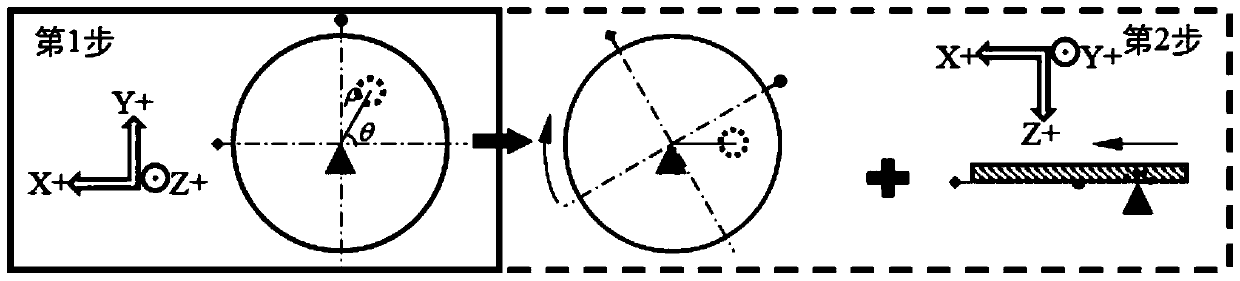
[0042] Step two, use the trial cutting me...

specific Embodiment approach 2

[0055] Specific implementation manner two: combination Figure 1 to Figure 4 To explain this embodiment, the fixed-point rotary cutting method of this embodiment is suitable for processing various types of materials. For example, in step 1, the material of the processed part can be either a plastic material used as a mold, such as duralumin 6061, mold steel, electroless nickel, etc., or a brittle material used as a separate part product, such as single Crystal germanium, single crystal silicon, etc. This setting enables the processing method to have a wider range of materials. The other composition and connection relationship are the same as in the first embodiment.

[0056] In step 1 of this embodiment, the material of the processed part is a plastic material or a brittle material; the type of the micro lens unit of the processed part is a concave mirror or a convex mirror.

specific Embodiment approach 3

[0057] Specific implementation mode three: combination Figure 1 to Figure 4 To illustrate this embodiment, a variety of processing tools of different shapes and materials can be selected in this embodiment. For example, in step 2, the tool material used can be single crystal diamond, nano twin diamond, or polycrystalline diamond and other tool materials used for ultra-precision processing of optical elements. The shape of the tool used can be either a formed turning tool or a non-formed turning tool, such as a circular arc cutting tool, a linear cutting tool and a pointed tool. If the tool used is a circular arc turning tool, the radius of the tool tip arc should not be greater than the minimum curvature radius of the microlens profile generatrix. This setting enables the machining method to have more flexible tool parameter settings and expands the scope of application of the method. Other components and connection relationships are the same as those in the first or second ...


PUM

PropertyMeasurementUnit
diameteraaaaaaaaaa
diameteraaaaaaaaaa

Abstract

The invention discloses a fixed-point rotary cutting method for off-axis microlens machining, and relates to a fixed-point rotary cutting method. The problem that the machining precision of a microlens is reduced due to the high-frequency motion which adversely affects the motion stability of a machine tool when the corner radius is compensated in the prior art, and the problem that planning of acutting track is difficult are solved. The method comprises the first step of adjusting the distance between the rotation center axis of a workpiece and the spindle axis of an ultra-precision machinetool to be controlled within 0.5 micrometer, the second step of controlling the radial distance between a tool tip of a tool and the rotation center axis of the workpiece to be within 0.5 micrometer by adopting a trial cutting method, the third step of moving the tool tip to the central axis position of a certain microlens unit of a microlens part to be machined through machine tool linkage, the fourth step of planning an actual cutting track, the fifth step of achieving cutting machining of one single microlens unit through machine tool linkage and the sixth step of repeatedly performing thethird, fourth and fifth steps till all the microlesn units on the surface are machined. The fixed-point rotary cutting method is used for off-axis microlens machining.

Description

Technical field [0001] The invention belongs to the technical field of ultra-precision processing of microlens optical elements, and specifically relates to a fixed-point rotary cutting method for off-axis microlens processing. Background technique [0002] The small and exquisite micro-lens parts can well meet the increasingly complex and sophisticated optical imaging and optical measurement needs. At present, the micro-lens parts have been widely used in military, medical, energy and other fields. With the expansion of the application breadth and the deepening of the application depth, the surface structure of the micro lens parts has been designed more and more complicated, and the materials used are more difficult to perform ultra-precision processing, such as single crystal germanium aspheric convex lens array parts, mold steel aspheric concave lens Array optical mold, etc. These complex micro-lens parts not only put forward new requirements for processing methods, but also...

Claims


Application Information

Patent Timeline
Patent Type & Authority Patents(China)
IPC IPC(8): B23B1/00
CPCB23B1/00
Inventor 赵清亮王爱博郭兵潘永成
Owner HARBIN INST OF TECH
Why Eureka
Try Eureka