A conveying device for waste disposal

A technology of conveying device and garbage disposal, applied in the direction of garbage conveying, storage device, garbage collection, etc., can solve the problems of increasing equipment cost and occupying space and compressing the garbage disposal volume of equipment, so as to reduce impact, improve extrusion effect and stability. high effect

Active Publication Date: 2021-07-16
MAANSHAN XINQIAO IND DESIGN CO LTD
View PDF6 Cites 0 Cited by
  • Summary
  • Abstract
  • Description
  • Claims
  • Application Information

AI Technical Summary

Problems solved by technology

[0003] The object of the present invention is to provide a conveying device for waste disposal, to solve the problem that in the prior art, the waste transported to the compression equipment cannot be pre-compressed to reduce the volume of waste without greatly increasing the equipment cost and occupying space. The problem of improving the garbage disposal capacity of compression equipment

Method used


Image

  • A conveying device for waste disposal
  • A conveying device for waste disposal
  • A conveying device for waste disposal

Examples


Embodiment 1

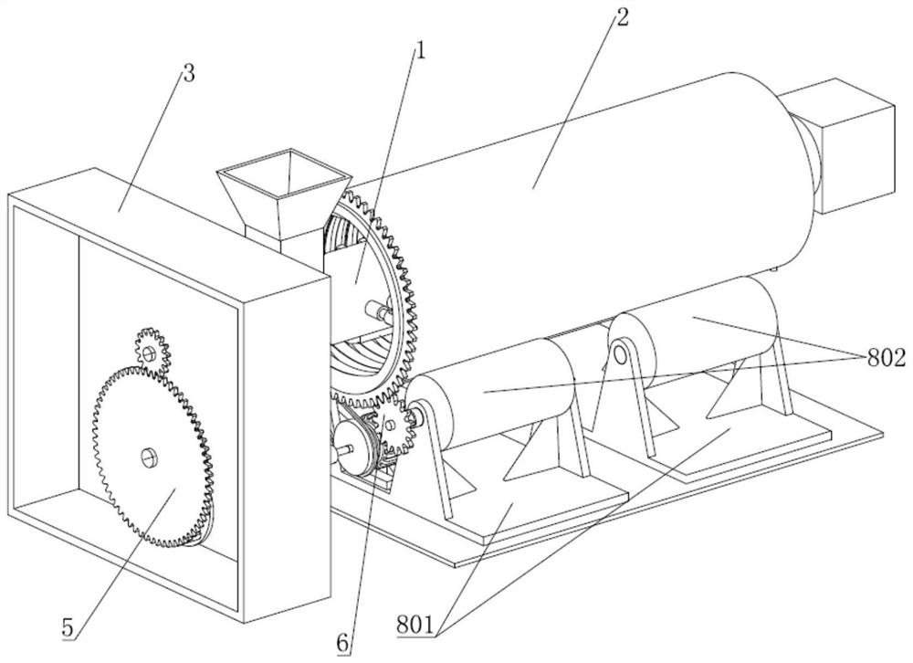
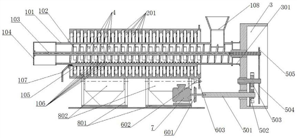
[0030] Such as Figure 1-5 with Figure 8-10 As shown, the present invention provides a conveying device for waste treatment, including a screw conveying mechanism 1, including a drive device 7, a conveying casing 101, and a helix disposed within the conveying cylinder 101 The conveying rod 103 is fixed to the helical transport rod 103, and the top of the conveying cylinder 101 is provided with a feed hopper 108, and the other end is provided with a discharge port 104.

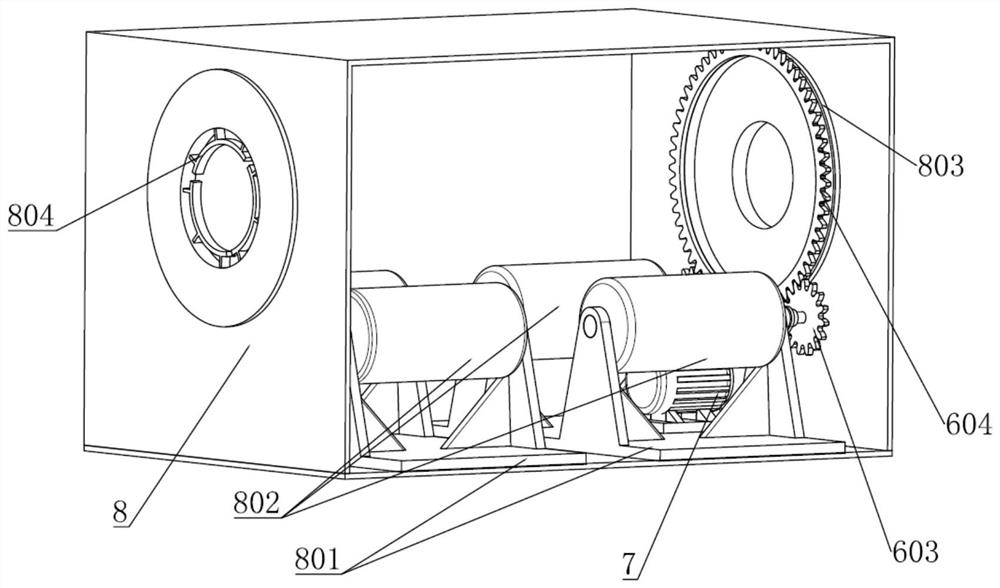
[0031]The conveying device further includes an outer extrusion sleeve 2, a pressure plate mechanism 4, a rotating mechanism, and a support housing 8, and the outer extrusion sleeve 2 is rotated in the support housing 8, the outer extrusion sleeve. The cartridge 2 concentric sleeve is outside the conveying cylindrical case 101 on the compression area of ​​the conveying cylindrical case 101, the drive device 7 drives the outer extruded sleeve 2 by the transmission mechanism; the conveying cylinder housing 101 The side...

Embodiment 2

[0043] The basic structure of this embodiment is similar to that of Example 1, and the difference is that the spiral rod drive mechanism 5. Such as Figure 6-7 As shown, in the present embodiment, a pair of arc shaped extrudation portions, the arc shaped extrudation portion occupies a quarter arc portion of the outer extruded sleeve 2, The arc shaped extrusion portion is configured on the outer extrusion sleeve 2, the active sprocket 601 is equal to the radius of the outer ring gear 604, and the cylindrical pin 5022 is paired and symmetric is located in the On the dial 502, a pair of convex arc 5023 is provided on the dial 502, and the convex lock arc 5023 is a quarter arc and symmetrically disposed, and the transmission gear one 504 and the drive gear two. The speed ratio of 505 is 1: 4. The groove 503 is provided with four pile stopping arc 5032 corresponding to the convex arc 5023 to realize the stationary wheel 503 in the gap cycle. In this case, the conveying state is longer t...


PUM


Abstract

The invention discloses a conveying device for garbage disposal, which comprises an outer extruding sleeve, a platen mechanism, a rotating mechanism and a supporting shell, the outer extruding sleeve is rotatably installed in the supporting shell, and the outer The extruding sleeve is concentrically sleeved outside the conveying shell and located in the compressed area of ​​the conveying shell, and the driving device drives the outer extruding sleeve to rotate through the transmission mechanism; the compressed area of ​​the conveying shell There are several sliding sleeves leading into the interior on the side. The pressing plate mechanism includes an arc-shaped pressing plate, a pressing bar and a roller. One end of the pressing bar is connected to the arc-shaped pressing plate and the other end is installed with the roller. The pressing bar One end connecting the rollers is connected to the conveying cylinder shell through a pressure spring, and the inner side of the outer extrusion sleeve is provided with a cam groove corresponding to the corresponding roller, and the cam groove has an arc-shaped extrusion part close to the center of its own circle . The invention can simultaneously realize the compression and dewatering transportation of the garbage during the process of conveying the garbage, so that the volume of the garbage received at the discharge end can be reduced.

Description

Technical field [0001] The present invention belongs to the field of garbage disposal, and more particularly to a conveying device for waste treatment. Background technique [0002] As the total amount of garbage is generated with a large number of garbage, it is the focus of social concern. Most of the garbage, including domestic waste, most of the garbage needs to be fill, so it needs to be compressed and removed from the garbage before landfill and remove air and moisture. . It is now generally compressed to waste compression devices that are generally used in garbage compression and removal. Since the non-pretreated garbage itself has a large amount of moisture and void, it is large, so when it is sent to the delivery device such as a spiral conveyor, it will quickly occupy the space of the compression device, resulting in a quantity of the compressed garbage. There is less, it reduces the efficiency of waste treatment, and if the garbage pre-compression device or drying devi...

Claims


Application Information

Patent Timeline
Patent Type & Authority Patents(China)
IPC IPC(8): B65F9/00B65G33/14B65G33/26B30B9/30B30B9/14
CPCB30B9/14B30B9/30B65F9/00B65G33/14B65G33/26
Inventor 李良柱张高惠鲍加胜许自发
Owner MAANSHAN XINQIAO IND DESIGN CO LTD
Why Eureka
Try Eureka