
Dynamic pressure measuring and phase lock device and method for tip of impeller of centrifugal compressor

A technology of centrifugal compressor and dynamic pressure, which is applied in the direction of measuring device, measuring force, adopting optical device, etc., to achieve the effect of reducing measurement system equipment, reducing the number of test equipment, and reducing test cost

Inactive Publication Date: 2019-11-05
CHINA SHIP DEV & DESIGN CENT
View PDF5 Cites 1 Cited by
  • Summary
  • Abstract
  • Description
  • Claims
  • Application Information

AI Technical Summary

Problems solved by technology

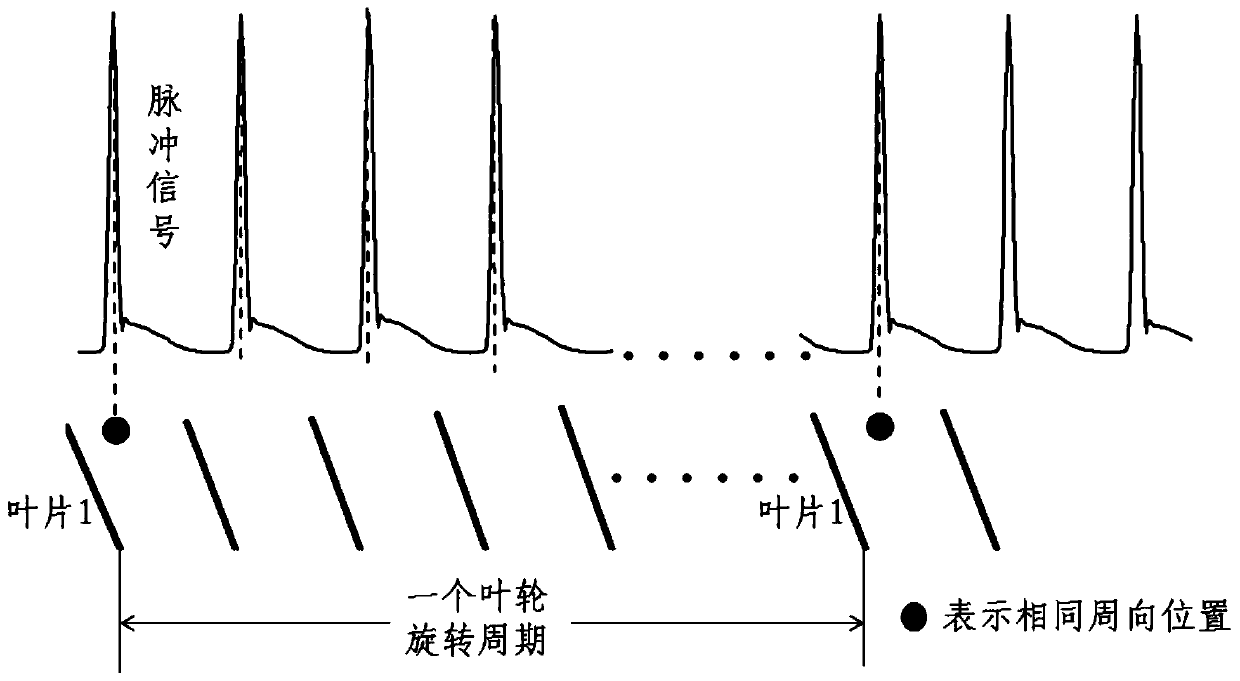
However, the above method can only produce the phase-locked average of the pressure at the same circumferential position (same phase) in multiple rotation cycles
Another phase-locking method is needed to study the leakage flow characteristics of the tip clearance: the phase-locking of the pressure at the same phase point in each flow channel of the impeller cannot be realized by installing a Hall sensor on the impeller shaft.

Method used


Image

  • Dynamic pressure measuring and phase lock device and method for tip of impeller of centrifugal compressor
  • Dynamic pressure measuring and phase lock device and method for tip of impeller of centrifugal compressor
  • Dynamic pressure measuring and phase lock device and method for tip of impeller of centrifugal compressor

Examples


Embodiment Construction

[0029] It should be understood that the specific embodiments described here are only used to explain the present invention, not to limit the present invention.

[0030] It should be noted that, in the description of the present invention, the terms "horizontal", "vertical", "upper", "lower", "front", "rear", "left", "right", "vertical", The orientation or positional relationship indicated by "horizontal", "top", "bottom", "inner", "outer", etc. is based on the orientation or positional relationship shown in the drawings, and is only for the convenience of describing the present invention and simplifying the description, and It is not to indicate or imply that the device or element referred to must have a particular orientation, be constructed in a particular orientation, or operate in a particular orientation, and thus should not be construed as limiting the invention. In addition, the terms "first", "second", etc. are used for descriptive purposes only, and should not be cons...


PUM


Abstract

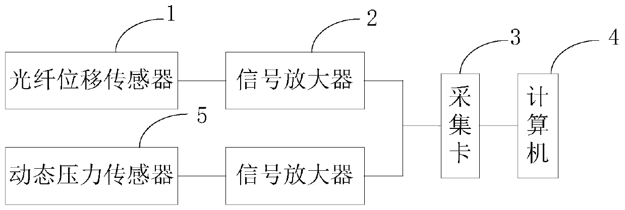
The invention discloses a dynamic pressure measuring and phase lock device and method for the tip of an impeller of a centrifugal compressor. The device comprise a fiber displacement sensor, a dynamicpressure sensor, signal amplifiers, an acquisition card and a computer, the fiber displacement sensor is connected with one acquisition channel of the acquisition card via one signal amplifier, the dynamic pressure sensor is connected with the other acquisition channel of the acquisition card via the other signal amplifier, the acquisition card is connected with the computer, the fiber displacement sensor and high frequency dynamic pressure sensor send sensed signals to the corresponding signal amplifiers respectively to make signal conversion, and then, data is acquired by the same acquisition card and displayed and stored by the computer. The device can measure the size of a gap of the tip, realize phase lock of the dynamic pressure of the same circumferential position within multiple rotation periods, and realize phase lock of dynamic pressure of same phase positions of different channels at the same time.

Description

technical field [0001] The invention relates to the technical field of test and measurement of centrifugal compressors, in particular to a dynamic pressure measurement and phase-locking device and method of impeller tops of centrifugal compressors. Background technique [0002] With the high speed and high pressure ratio of the centrifugal impeller, the blade height gradually decreases. However, due to the problem of machining accuracy and the consideration of the operation safety of the centrifugal impeller, the blade tip clearance should not be too small, resulting in an increase in the relative blade tip clearance (the ratio of the blade tip clearance to the blade height), and the influence of the tip clearance leakage flow will be more prominent. The research on the characteristics of leakage flow is more important. [0003] A dynamic pressure sensor is arranged on the surface of the casing, and the dynamic pressure on the top of the impeller is measured experimentally....

Claims


Application Information

Patent Timeline
Patent Type & Authority Applications(China)
IPC IPC(8): G01B11/02G01B11/14G01L1/00H03L7/085
CPCG01B11/026G01B11/14G01L1/00H03L7/085
Inventor 赵会晶吴毅吕海财周雅杰
Owner CHINA SHIP DEV & DESIGN CENT
Learn More