
Induction coil set and reaction chamber

A technology of induction coils and reaction chambers, applied to circuits, discharge tubes, electrical components, etc., can solve problems such as sputtering pollution and affect process results, and achieve the goals of reducing sputtering, improving process results, and reducing capacitive coupling Effect

Active Publication Date: 2021-04-09
BEIJING NAURA MICROELECTRONICS EQUIP CO LTD
View PDF6 Cites 0 Cited by
  • Summary
  • Abstract
  • Description
  • Claims
  • Application Information

AI Technical Summary

Problems solved by technology

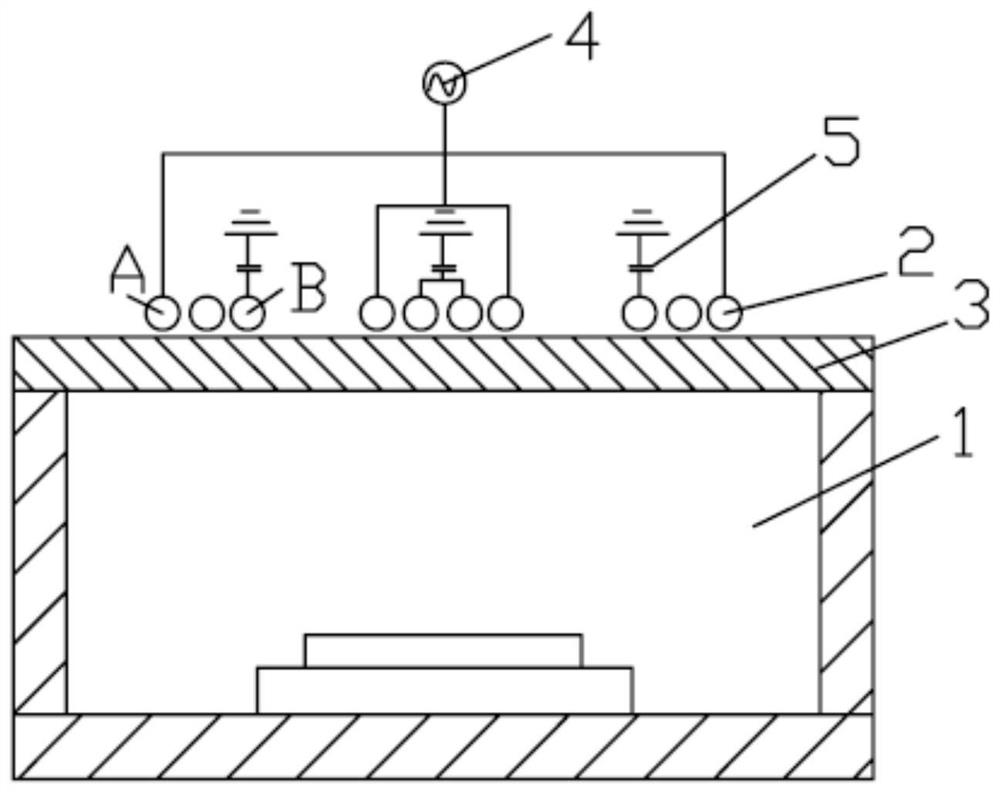
[0004] However, since the potential of the planar coil 2 at the power input terminal A and the series capacitor terminal B is relatively high, and the distance from the plasma is relatively close (the vertical distance between the power input terminal A and the serial capacitor terminal B is relatively small), the power input terminal A and the serial capacitor terminal A strong capacitive coupling is formed between the capacitor terminals B and the ground, which may cause a high-voltage sheath to be formed on the lower surface of the dielectric window 3, and the high-voltage sheath will cause the lower surface of the dielectric window 3 to be sputtered, thereby Generates sputtering contamination that affects process results

Method used


Image

  • Induction coil set and reaction chamber
  • Induction coil set and reaction chamber
  • Induction coil set and reaction chamber

Examples


Embodiment Construction

[0047] In order for those skilled in the art to better understand the technical solution of the present invention, the induction coil set and the reaction chamber provided by the present invention will be described in detail below with reference to the accompanying drawings.

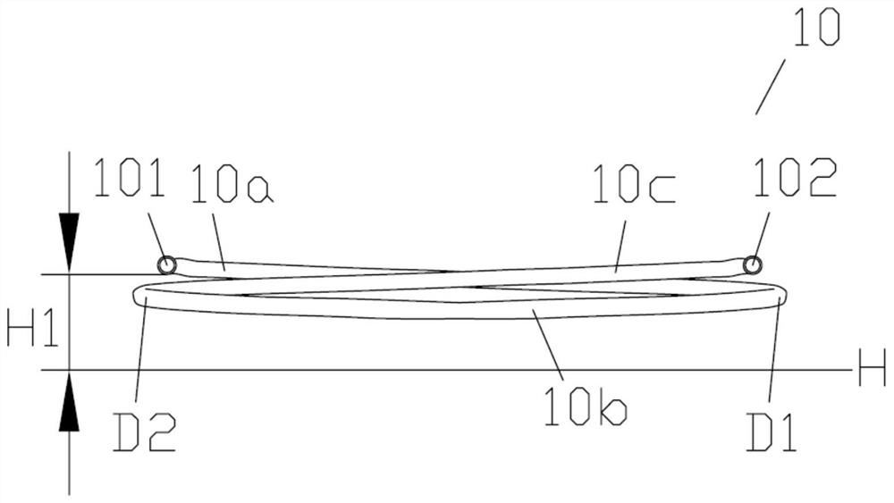
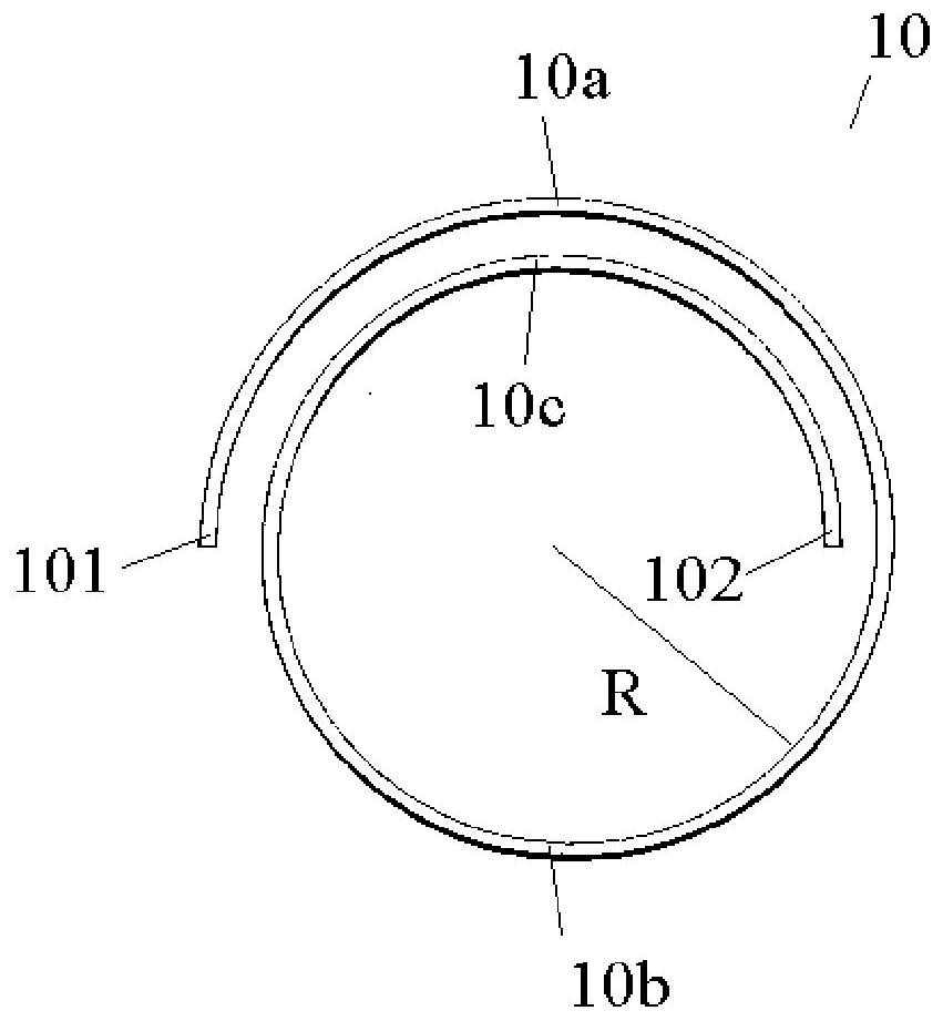
[0048] Please also refer to figure 2 and image 3, the induction coil set provided by the first embodiment of the present invention includes an induction coil 10 arranged above the dielectric window of the reaction chamber, and by applying radio frequency power to the induction coil 10, the process gas in the reaction chamber can be excited to form plasma. Two ends (101, 102) of the induction coil 10 are respectively a power input terminal and a ground terminal, wherein the power input terminal is used for electrical connection with a radio frequency power supply; the ground terminal is used for grounding.

[0049] In practical applications, a capacitor can usually be connected in series between the g...


PUM


Abstract

The present invention provides an induction coil group and a reaction chamber. The induction coil group includes an induction coil arranged above the dielectric window of the reaction chamber. The two ends of the induction coil are power input terminals and ground terminals respectively. The vertical distance between the two ends and the dielectric window is greater than the vertical distance between the part between the two ends of the induction coil and the dielectric window. The induction coil group and the reaction chamber provided by the present invention can reduce the capacitive coupling at both ends of the induction coil on the premise of ensuring that the coupling strength of the radio frequency magnetic field meets the requirements, thereby reducing the sputtering of the dielectric window and improving the process results .

Description

technical field [0001] The invention relates to the field of semiconductor manufacturing, in particular to an induction coil group and a reaction chamber. Background technique [0002] RF inductively coupled plasma (Inductive Coupled Plasma, hereinafter referred to as ICP) has higher discharge efficiency than Capacitance Coupled Plasma (hereinafter referred to as CCP), and can produce high-density plasma at lower pressure (1-100mTorr). Plasma, therefore, ICP equipment is widely used in etching, deposition and other processes in the semiconductor field. In the ICP device, the radio frequency current flowing in the induction coil can excite the radio frequency magnetic field in space, and generate an angular electric field in the plasma to heat electrons through Faraday electromagnetic induction, thereby generating a high-density plasma. [0003] figure 1 It is a sectional view of an existing ICP reaction chamber. see figure 1 , the reaction chamber 1 includes a dielectric...

Claims


Application Information

Patent Timeline
Patent Type & Authority Patents(China)
IPC IPC(8): H01J37/32
CPCH01J37/3211
Inventor 牛晨韦刚苏恒毅杨京
Owner BEIJING NAURA MICROELECTRONICS EQUIP CO LTD
Learn More