
Semiconductor package structure and manufacturing method thereof

A technology of packaging structure and manufacturing method, applied in semiconductor/solid-state device manufacturing, semiconductor devices, semiconductor/solid-state device components, etc., can solve the problems of substrate exposure, yield problem, and package body easily damped, and achieve stable packaging structure , the effect of enhancing the heat dissipation capacity

Active Publication Date: 2021-06-29
JCET GROUP CO LTD
View PDF6 Cites 0 Cited by
  • Summary
  • Abstract
  • Description
  • Claims
  • Application Information

AI Technical Summary

Problems solved by technology

However, using this method to dissipate heat, if it is necessary to back gold on a wafer with a thickness less than 180um after thinning, it needs to be supported by expensive temporary bonding.
At the same time, another solution is to use substrate-embedded chips, but there are also serious yield problems
[0004] The above two heat dissipation structures and methods may have the problem of substrate exposure, and the reliability of the package structure is relatively low, and generally cannot pass the requirements of moisture sensitivity level 1 (MSL1), making the package body susceptible to moisture

Method used


Image

  • Semiconductor package structure and manufacturing method thereof
  • Semiconductor package structure and manufacturing method thereof
  • Semiconductor package structure and manufacturing method thereof

Examples


Embodiment 1

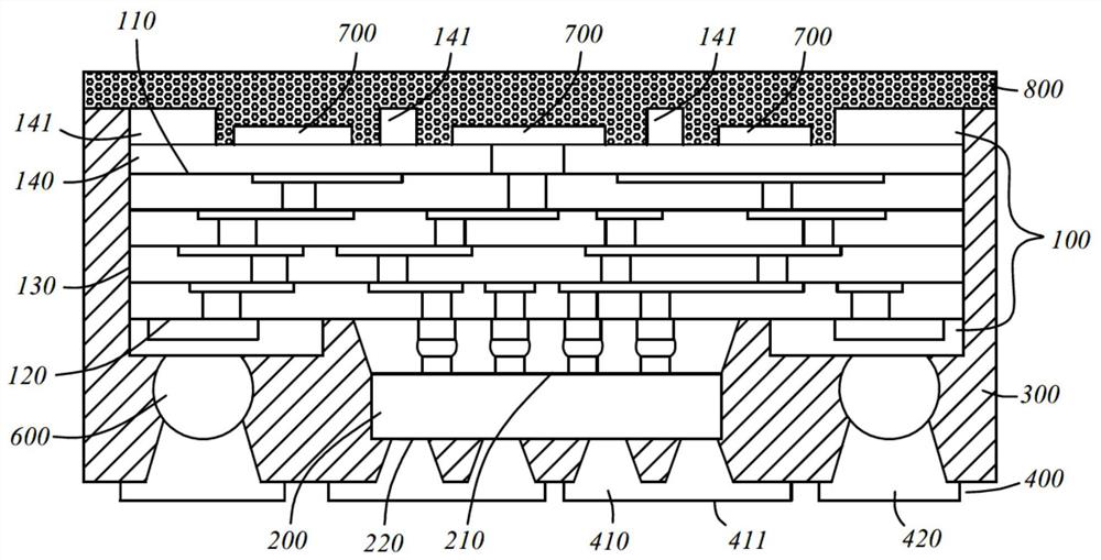
[0103] ginseng figure 1 As shown, in the first embodiment of the present invention, the semiconductor package structure includes a main substrate 100 , a chip 200 , a plastic encapsulation layer 300 and a back gold layer 400 .

[0104] Specifically, the main body substrate 100 includes an upper surface circuit 110, an opposite lower surface circuit 120, and a side surface 130 connecting the upper surface circuit 110 and the lower surface circuit 120, and the upper surface circuit 110 and the lower surface circuit 120 of the main body substrate 100 It should be noted that the main substrate 100 mentioned in the embodiment of the present invention can be stacked using a homogeneous or heterogeneous circuit board structure, and the main body is realized by setting an electrical connection structure in the circuit board and stacking each other. The upper and lower sides of the substrate 100 are electrically connected.

[0105] At the same time, the chip 200 includes a first conne...

Embodiment 2

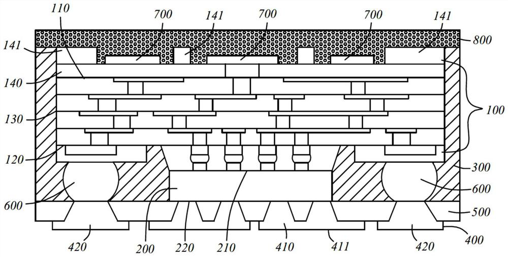
[0113] ginseng figure 2 As shown, the main difference between the second embodiment of the present invention and the first embodiment is that the plastic encapsulation layer 300 does not completely cover the chip 200 and the 3D connection part 600, and the plastic encapsulation layer 300 is flush with the second connection surface 220, The 3D connection part 600 is at least partially exposed.

[0114] At the same time, the semiconductor package structure also includes a stress-buffering dielectric layer 500 covering both the second connection surface 220 and the plastic encapsulation layer 300 , and the first metal connection part 410 is connected to the second connection surface 220 through the stress-buffering dielectric layer 500 , and the extended surface 411 protrudes out of the stress-buffering dielectric layer 500 .

[0115] In the second embodiment of the present invention, the protection of the chip 200 is enhanced by covering the second connection surface 220 and t...

Embodiment 3、 Embodiment 4 and Embodiment 5

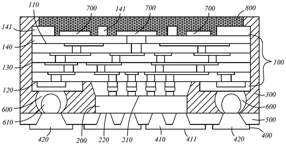
[0118] combine image 3 , Figure 4 with Figure 5 As shown, on the basis of the second embodiment of the present invention, by changing the specific structure of the 3D connection part 600, the present invention also proposes a third embodiment, a fourth embodiment and a fifth embodiment.

[0119] ginseng image 3 As shown, in the third embodiment, the 3D connection part 600 is provided with a metal heat sink 610, specifically, the 3D connection part 600 is set as a solder ball, the metal heat sink 610 is set as a copper core ball, and the copper core ball is wrapped The 3D connection part 600 is formed by covering and inside the solder ball, which enhances the heat dissipation performance after the connection between the 3D connection part 600 and the second metal connection part 420 .


PUM


Abstract

The present invention proposes a semiconductor packaging structure, which is characterized in that the semiconductor packaging structure includes: a main body substrate, including an upper surface circuit, a lower surface circuit, and a side surface connecting the upper surface circuit and the lower surface circuit, and the upper surface The circuit is electrically connected to the circuit on the lower surface; the chip includes a first connecting surface and a second connecting surface oppositely arranged, and the first connecting surface is electrically connected to the circuit on the lower surface; the plastic sealing layer completely covers the The side surface of the substrate, and the plastic encapsulation layer at least partially covers the lower surface circuit and the chip; the back gold layer includes at least one first metal connection part connected to the second connection surface of the chip, the first The metal connection part includes an extension surface extending and protruding out of the plastic sealing layer, and the sum of the areas of the extension surfaces is greater than the area of ​​the second connection surface. The invention solves the heat dissipation problem of the chip while reducing the production cost, and meets and exceeds the requirement of level 3 moisture sensitivity of the packaging body.

Description

technical field [0001] The invention belongs to the field of semiconductor manufacturing, and in particular relates to a semiconductor packaging structure and a manufacturing method thereof. Background technique [0002] In the existing chip packaging structure, due to the heat dissipation requirements of the control chip and the package body, metal (back gold) is generally deposited on the back of the chip to reduce thermal resistance. [0003] At the same time, for large chips with high heat dissipation requirements, it is currently mainly carried out by direct back gold deposition and molding on the wafer. However, using this method to dissipate heat, if it is necessary to back gold on a wafer with a thickness of less than 180um after thinning, it needs to be supported by expensive temporary bonding. At the same time, another solution is to use substrate-embedded chips, but there are also serious yield problems. [0004] The above two heat dissipation structures and met...

Claims


Application Information

Patent Timeline
Patent Type & Authority Patents(China)
IPC IPC(8): H01L23/31H01L23/52H01L21/56
CPCH01L21/56H01L25/18H01L23/3128H01L24/02H01L23/564H01L23/3672H01L2224/02331H01L2224/02381H01L2224/73204H01L2224/18
Inventor 林耀剑刘硕周莎莎陈建陈雪晴
Owner JCET GROUP CO LTD
Learn More