
Film coating fixture

A jig and workpiece disk technology, applied in the field of coating jig, can solve the problems of poor optical performance of lenses, poor coating effect, complicated operation, etc., and achieve the effect of easy cleaning and maintenance, avoiding multiple clamping and avoiding pollution.

Pending Publication Date: 2019-11-08
ZHEJIANG SUNNY OPTICAL CO LTD
View PDF0 Cites 1 Cited by
  • Summary
  • Abstract
  • Description
  • Claims
  • Application Information

AI Technical Summary

Problems solved by technology

As a result, the coating effect is poor, and the optical performance of the lens is not good
In addition, with the existing coating jigs, after coating one surface of the lens, some need to remove the lens and turn it over before coating the other side, which is cumbersome and inefficient.

Method used


Image

  • Film coating fixture
  • Film coating fixture
  • Film coating fixture

Examples


Embodiment approach

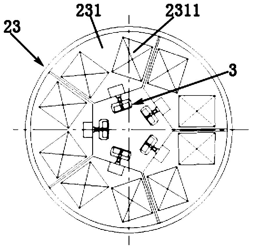
[0046] like Figure 4 As shown, according to the second embodiment of the present invention, the workpiece disk 23 is a disc-shaped structure, the workpiece disk 23 is integrally formed, and the workpiece sheet 23 is provided with a lens clamping area 2311 . In this embodiment, the lens clamping area 2311 is circular, and the rotating shaft 22 is connected to the outer tangent point of the workpiece disk 23 , so that the workpiece disk 23 can also be driven to rotate. The workpiece disc 23 is connected with the overturning system 3, and the overturning system 3 can overturn the workpiece disc 23 by 180°.

[0047] According to the concept of the present invention, the shape of the lens clamping area 2311 is not limited, and besides the above-mentioned rectangle and circle, it can also be a direction or other polygonal shapes. The overturning system 3 can be a rotary cylinder mechanism, a gear drive mechanism or a connecting rod drive mechanism, etc., as long as the mechanism t...


PUM


Abstract

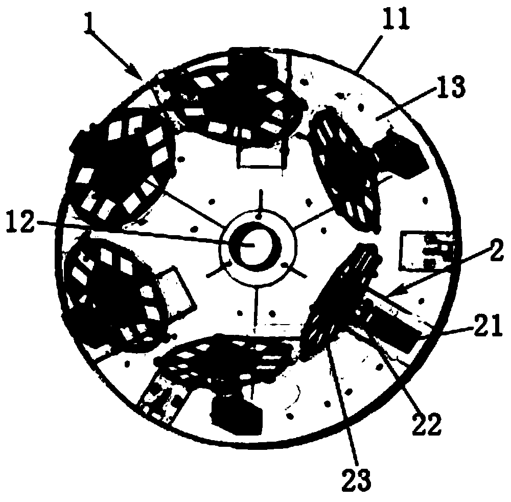
The present invention relates to a film coating fixture, comprising a revolution system, a rotation system and a turnover system; the revolution system comprises a revolution support, a revolution shaft located on the central position of the revolution support and connected with the revolution support, and a guard plate supported on the revolution support; the rotation system is fixed on the guardplate, and comprises a fixing base, a rotating shaft connected to the fixing base and a workpiece plate that is connected to and rotatable with the rotating shaft; the revolution shaft drives the rotation system to rotate, meanwhile the rotating shaft drives the workpiece plate to rotate; the turnover system is connected with the workpiece plate and used for driving the workpiece plate to turn by180 degrees. The film coating fixture of the present invention can effectively improve the effect of film coating, and also can increase the efficiency of film coating.

Description

technical field [0001] The invention relates to the technical field of optical coating, in particular to a coating jig. Background technique [0002] With the development of the optical industry, more and more types of products need to be coated to obtain specific optical properties. For the coating of optical lenses, vacuum coating equipment is usually used in the industry for evaporation coating to complete the deposition of film layers on the surface of the substrate. [0003] Vacuum coating equipment is generally a large-scale machine chamber, and the large-scale coating fixtures usually used are umbrella-shaped. Coated products need to be loaded with a jig and placed on the fan-shaped plate of the coating machine for coating. The evaporated molecules of the vacuum coating film material move along a straight line, and the different curvature lenses, aspheric lenses and different areas have different evaporation incident angles, resulting in a large difference in the fi...

Claims


Application Information

Patent Timeline
IPC IPC(8): C23C14/50C23C14/24
CPCC23C14/505C23C14/24
Inventor 蒯泽文
Owner ZHEJIANG SUNNY OPTICAL CO LTD
Learn More