Low-stiffness magnetic suspension gravity compensator, driving device and six-degree-of-freedom micro-motion stage

A gravity compensation and driving device technology, which is applied to the magnetic attraction or thrust holding device, electromechanical device, electrical components, etc., can solve the problems of reduced stiffness, low stiffness, and high stiffness of the six-degree-of-freedom micro-motion table, etc., to achieve good Vibration damping and vibration isolation effect, effect of low vertical stiffness

Active Publication Date: 2019-11-08
HUAZHONG UNIV OF SCI & TECH
View PDF4 Cites 8 Cited by
  • Summary
  • Abstract
  • Description
  • Claims
  • Application Information

AI Technical Summary

Problems solved by technology

[0005] Aiming at the above defects or improvement needs of the prior art, the present invention provides a low-stiffness magnetic levitation gravity compensator, a driving device and a six-degree-of-freedom micro-motion stage. It acts as a gravity compensator, thereby reducing the stiffness. The moving element structure of the magnetic levitation gravity compensator is combined with two sets of coils to form a driving device, and four symmetrically arranged gravity compensators and driving devices constitute a six-degree-of-freedom micro-motion table. Therefore, the driving device is light in weight, thereby solving the technical problems of high rigidity and complex structure of the six-degree-of-freedom micro-motion table in the prior art

Method used


Image

  • Low-stiffness magnetic suspension gravity compensator, driving device and six-degree-of-freedom micro-motion stage
  • Low-stiffness magnetic suspension gravity compensator, driving device and six-degree-of-freedom micro-motion stage
  • Low-stiffness magnetic suspension gravity compensator, driving device and six-degree-of-freedom micro-motion stage

Examples


Embodiment Construction

[0039] In order to make the object, technical solution and advantages of the present invention clearer, the present invention will be further described in detail below in conjunction with the accompanying drawings and embodiments. It should be understood that the specific embodiments described here are only used to explain the present invention, not to limit the present invention. In addition, the technical features involved in the various embodiments of the present invention described below can be combined with each other as long as they do not constitute a conflict with each other.

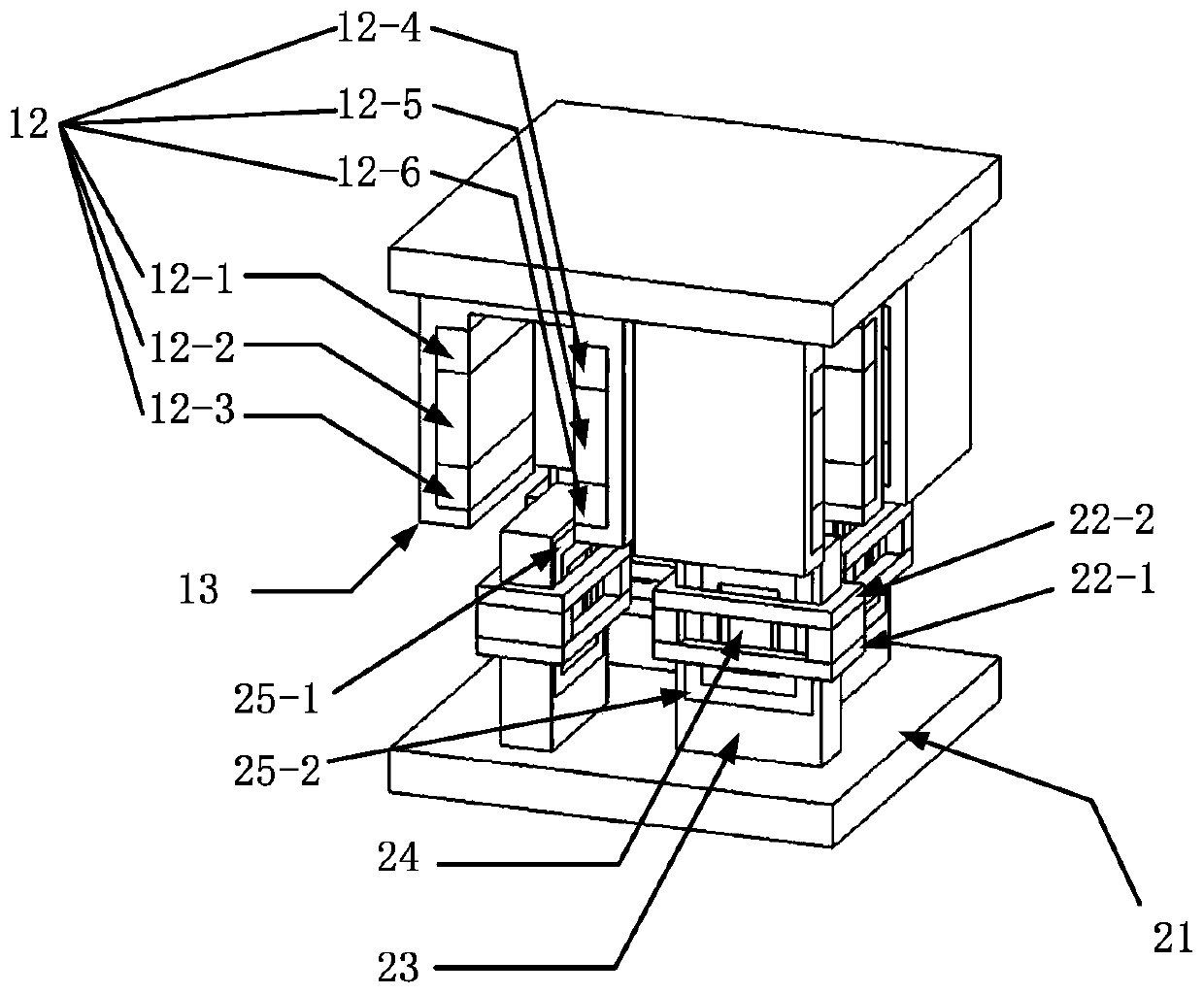
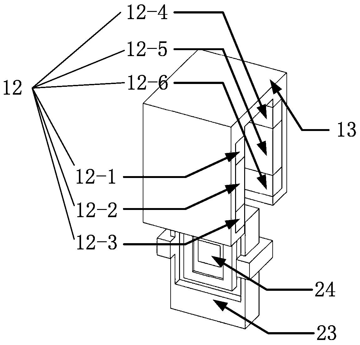
[0040]The invention provides a low-stiffness magnetic levitation gravity compensator, a driving device and a six-degree-of-freedom micro-motion stage. By making the permanent magnet in the center of the stator receive the magnetic attraction force and the magnetic repulsion force in the air gap magnetic field generated by the permanent magnet array block of the mover, In order to realize the gra...


PUM


Abstract

The invention discloses a low-stiffness magnetic suspension gravity compensator, a driving device and a six-degree-of-freedom micro-motion stage, belonging to the field of semiconductor manufacturingassembly. The gravity compensator comprises a rotor structure and a stator structure; the rotor structure is composed of a magnet bracket and a plurality of pairs of permanent magnet array blocks arranged at the side wall of the magnet bracket in parallel; the stator structure is formed by a stator base, a coil bracket and a central permanent magnet; the center permanent magnet of the stator is subjected to magnetic attraction and magnetic repulsion in the air gap magnetic field generated by the rotor permanent magnet array blocks to achieve the gravity compensation of the structure of the rotor and the load. Two sets of coils are arranged at the left and right sides of the grooves of the coil bracket and the upper and lower portions of the boss to form a driving device with the rotor structure of the magnetic suspension gravity compensator so as to achieve the horizontal and vertical two-degree-of-freedom combined driving; four gravity compensators which are arranged symmetrically anddriving devices form a six-degree-of-freedom micro-motion stage. The low-stiffness magnetic suspension gravity compensator, the driving device and the six-degree-of-freedom micro-motion stage achievethe near-zero stiffness magnetic suspension of the rotor structure and the load in a wide range of motion, and the combined driving device has a simple structure and a light weight.

Description

technical field [0001] The invention belongs to the technical field related to semiconductor manufacturing and assembly, and more specifically relates to a low-rigidity magnetic levitation gravity compensator, a driving device and a six-degree-of-freedom micro-motion stage. Background technique [0002] Today's widespread use of chips has brought about earth-shaking changes in people's lives, but the lithography machines that process and manufacture chips are difficult to manufacture and have high precision. Therefore, only a few companies in the world can produce them. At the same time, lithography machines are the most critical. The two subsystems are the ultra-precise exposure optical system and the ultra-precise workpiece stage system, which respectively represent the technical peaks of ultra-precise optics and ultra-precise mechanics. Therefore, the research on the next-generation lithography machine technology is the most advanced topic in the current microelectronics ...

Claims


Application Information

Patent Timeline
IPC IPC(8): H02N15/00H02K53/00
CPCH02K53/00H02N15/00
Inventor 曾理湛刘凯陈学东
Owner HUAZHONG UNIV OF SCI & TECH
Why Eureka
Try Eureka