Image reconstruction method and device, computer equipment and storage medium

A technology for computer equipment and image reconstruction, applied in the field of medical devices, can solve the problems of high data transmission bandwidth requirements, long transmission time, and reduced image reconstruction speed, so as to shorten the transmission time, speed up image reconstruction speed, and reduce data transmission. The effect of bandwidth

Pending Publication Date: 2019-11-12
SHANGHAI UNITED IMAGING HEALTHCARE
View PDF6 Cites 2 Cited by
  • Summary
  • Abstract
  • Description
  • Claims
  • Application Information

AI Technical Summary

Problems solved by technology

However, this method needs to transmit both time-of-flight conforming to photons to the image reconstruction machine, which requires high data transmission bandwidth, and the transmission takes a long time, which reduces the image reconstruction speed

Method used


Image

  • Image reconstruction method and device, computer equipment and storage medium
  • Image reconstruction method and device, computer equipment and storage medium
  • Image reconstruction method and device, computer equipment and storage medium

Examples


Embodiment Construction

[0037] In order to make the purpose, technical solution and advantages of the present application clearer, the present application will be further described in detail below in conjunction with the accompanying drawings and embodiments. It should be understood that the specific embodiments described here are only used to explain the present application, and are not intended to limit the present application.

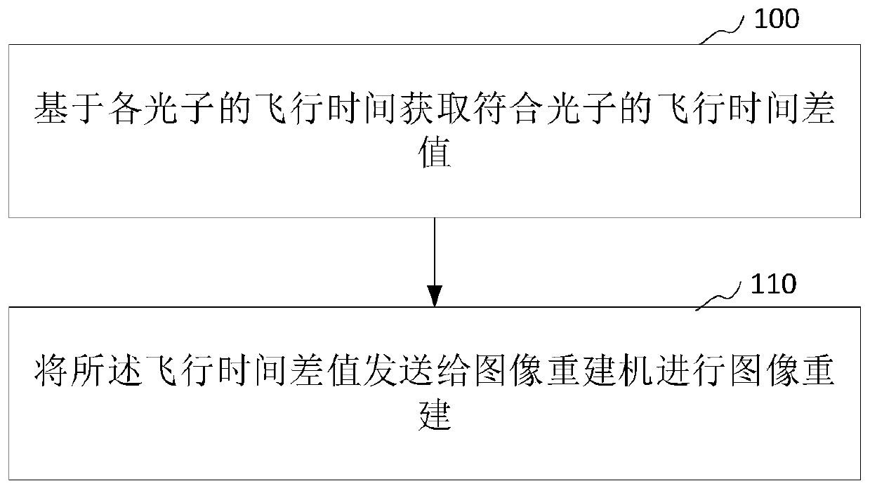
[0038] see figure 1 , figure 1 It is a schematic diagram of an image reconstruction method according to an embodiment of the present invention.

[0039] In this embodiment, the image reconstruction method includes:

[0040] Step 100, based on the time-of-flight of each photon, the time-of-flight difference of the corresponding photons is obtained.

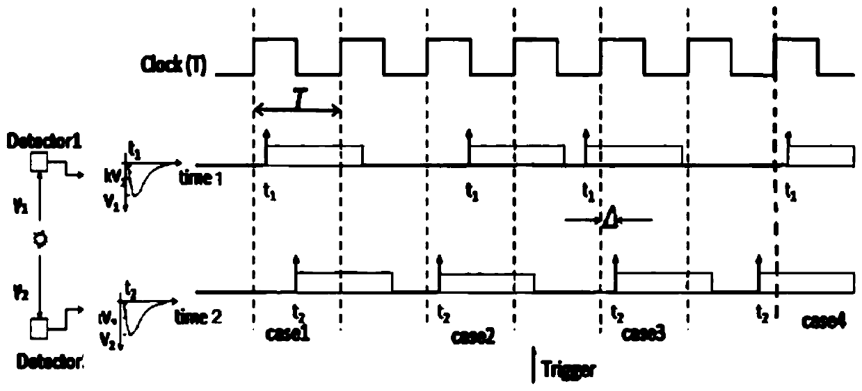
[0041] Exemplarily, the acquiring the time-of-flight difference of the coincident photons based on the time-of-flight of each photon includes calculating the time-of-flight difference of the coincident photons by using a fie...


PUM


Abstract

The application relates to an image reconstruction method and device, computer equipment and a storage medium. The method comprises the following steps of based on the flying time of each photon, obtaining the flying time difference value of coincidence photons; and transmitting the flying time difference value to an image reconstruction machine, and performing image reconstruction. According to the image reconstruction method and the device, the computer equipment and the storage medium disclosed by the invention, through the method comprising the following steps of based on the flying time of each photon, obtaining the flying time difference value of the coincidence photons, transmitting the flying time difference value to the image reconstruction machine, and performing image reconstruction, the calculation of the flying time difference value is completed before data is transmitted to the image reconstruction machine, and then transmitting the flying time difference value to the image reconstruction machine is only needed, so that the data transmission band width is effectively reduced, the transmission time consumption is shortened, and the image reconstruction speed is accelerated.

Description

technical field [0001] The present application relates to the technical field of medical devices, in particular to an image reconstruction method, device, computer equipment and storage medium. Background technique [0002] Positron Emission Tomography (PET) is a three-dimensional imaging non-destructive testing technique that uses positron radioactive isotope-labeled compounds injected into organisms to measure their spatial distribution and time characteristics in vitro. High precision, good accuracy and accurate positioning. [0003] The working principle of PET is: label the radionuclides that emit positrons on the compounds that can participate in the blood flow or metabolic process of human tissues, inject the radionuclides marked with compounds with positrons into the subjects, and let the subjects PET imaging was performed within the effective field of view of PET. During PET scanning, the positrons emitted by the radionuclide move about 1 mm in the body and then c...

Claims


Application Information

Patent Timeline
Patent Type & Authority Applications(China)
IPC IPC(8): A61B6/03G06T11/00
CPCA61B6/037A61B6/52G06T11/003G06T2210/41
Inventor 郑威李俊王素铭杨隆梓付亚光
Owner SHANGHAI UNITED IMAGING HEALTHCARE
Why Eureka
Try Eureka