Machine-mounted splitting machine

A technology of splitting machine and bearing frame, which is applied in the direction of discharging machinery, earth-moving drilling and mining, etc., can solve the problems of cracking of skin cracks, reducing oil pressure, and inconvenience.

Active Publication Date: 2019-11-12
江门市新会区泰盛石场有限公司
View PDF16 Cites 1 Cited by
  • Summary
  • Abstract
  • Description
  • Claims
  • Application Information

AI Technical Summary

Problems solved by technology

[0002] The airborne splitting machine is widely used in ground concrete crushing, rock mining crushing, etc. Its working principle is to put the splitting head with wedge-shaped block into the hole (pre-processed) on the target body, and through the external There is oil pressure to pressurize the conical cylinder in the splitting head to open the wedge-shaped block laterally to achieve the effect of splitting the target body, but this splitting method still has the following disadvantages: 1. The splitting power source is driven by hydraulic oil , the long-term use of the machine will increase the oil temperature, thereby reducing the oil pressure, and at the same time the oil circuit system is complicated and the maintenance cost is high; 2. When large rock blocks are required, a large number of holes are usually drilled on the side of the rock to insert the splitting head and then use The splitting of the wedge-shaped block is driven by hydraulic pressure. Due to the slow hydraulic oil circuit, cracking of the skin cracks often occurs. At the same time, the overall rock extraction and rock separation require separate equipment operation, which is extremely inconvenient; 3. The current splitting machine only has Splitting function, without the function of stone material transfer, the invention provides an airborne splitting machine

Method used


Image

  • Machine-mounted splitting machine
  • Machine-mounted splitting machine
  • Machine-mounted splitting machine

Examples


Embodiment approach

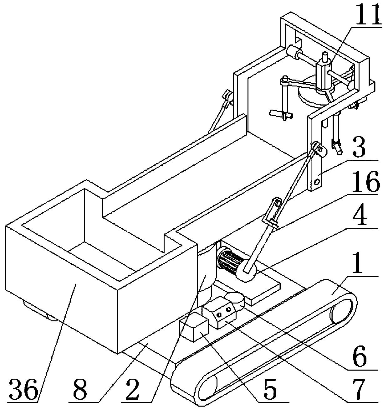
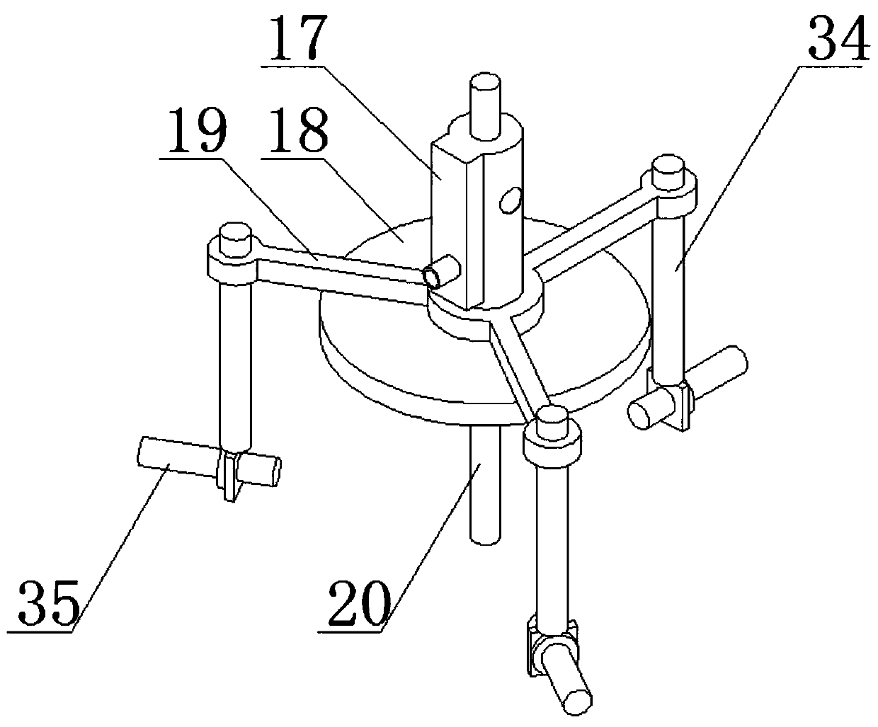
[0027] As a preferred embodiment of the present invention, a surrounding coil 37 is provided in the electromagnet disk 18.

[0028] As a preferred embodiment of the present invention, the magnetic induction coil 22 is connected to the high-power capacitor 6 and the virtual cathode tube 23 through a wire, and the virtual cathode tube 23 is connected to the microwave transmitting antenna 29 through a wire.

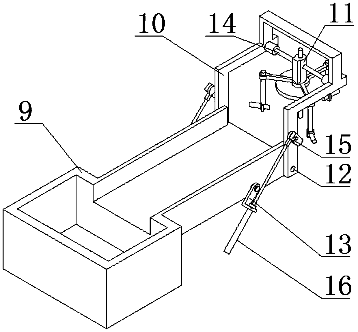
[0029] As a preferred embodiment of the present invention, the central splitting head 20 and the lateral splitting head 35 have the same size and specifications.

[0030] As a preferred embodiment of the present invention, the control button includes a start button, a weak magnetic flux button one, a weak magnetic flux button two, a displacement button, a center split button and a horizontal split button, and the control button is connected to The driving motor, the movable oil cylinder 16, the magnetic induction coil 22, the surrounding coil 37 and the igniter 25 are connected, an...


PUM


Abstract

The invention discloses a machine-mounted splitting machine. The machine-mounted splitting machine comprises a track base, a rotating table, a bearing combination, a hydraulic system, a storage battery, a high-power capacitor and a control panel, the bearing combination is connected with the track base through the rotating table, a supporting table plate is arranged on the track base, the hydraulic system, the storage battery, the high-power capacitor and the control panel are all arranged on the supporting table plate, the bearing combination comprises a turnover counterweight box, a movablebearing frame and a splitting combination, and a rotating shaft and a rotating plate are arranged on the turnover counterweight box. The current in a magnetic induction coil is increased through explosive blasting in a magnetic flux compressing mode, the current is conducted into a virtual cathode tube, high-frequency electric waves are generated in a resonance mode, finally, a microwave antenna transmits electromagnetic pulse waves in the designated direction to impact and push a wedge block to realize the splitting function, through the method, powerful impact force can be generated instantly, and stone can be directly disengaged.

Description

Technical field [0001] The invention relates to the technical field of rock splitting equipment, in particular to an airborne splitting machine. Background technique [0002] Airborne splitter is widely used in ground concrete crushing, rock mining crushing, etc. Its working principle is to put a splitting head with a wedge block into the hole (pre-processed) on the target body, and pass the external Oil pressure pressurizes the conical cylinder in the splitting head to open the wedge block laterally to achieve the function of splitting the target body. However, this splitting method has the following shortcomings: 1. The splitting power source is driven by hydraulic oil. , The long-term use of the machine will increase the oil temperature, thereby reducing the oil pressure. At the same time, the oil circuit system is complicated and the maintenance cost is high; 2. When large rocks are required, a large number of holes are usually drilled in the rock side to insert the splitting...

Claims


Application Information

Patent Timeline
Patent Type & Authority Applications(China)
IPC IPC(8): E21C37/04E21C37/18
CPCE21C37/04E21C37/18
Inventor 邢培培
Owner 江门市新会区泰盛石场有限公司
Why Eureka
Try Eureka