Wireless charging device and system for an autonomous underwater vehicle, and a coil winding method

An underwater vehicle, wireless charging technology, applied in the direction of transformer/inductor coil/winding/connection, coil manufacturing, circuit device, etc., can solve the problems of magnetic coupling structure large leakage, not given, serious electromagnetic radiation and other problems , to meet the requirements of reducing docking accuracy, small charging capacity, and small internal space.

Active Publication Date: 2019-11-12
HARBIN INST OF TECH AT WEIHAI +1
View PDF5 Cites 1 Cited by
  • Summary
  • Abstract
  • Description
  • Claims
  • Application Information

AI Technical Summary

Problems solved by technology

[0003] Some wireless charging devices used to charge AUVs in the prior art are installed at the bottom of the AUV to avoid electromagnetic interference to internal equipment, which requires changing the shape of the AUV and charging When using AUV, it is necessary to accurately locate the center position of the transmitter; there are also some wireless charging devices that do not need to change the shape, but are highly sensitive to misalignment, and have a greater impact on non-aligned charging, and the heavier magnetic core increases the weight of the AUV itself; In addition, some wireless charging devices use planar coils, which are less sensitive to misalignment. However, the magnetic coupling structure of the planar coil has large magnetic leakage on the back, and the problem of electromagnetic radiation is serious. It is necessary to install a shielding layer and occupy a large space in the AUV battery compartment.
[0004]Based on this, how to improve the power transmission effect of the existing wireless charging device to the AUV and reduce the power transmission effect of the existing wireless charging device on the basis of avoiding electromagnetic interference to the internal equipment of the AUV. Volume, improve dislocation coupling, no effective solution is given in the prior art

Method used


Image

  • Wireless charging device and system for an autonomous underwater vehicle, and a coil winding method
  • Wireless charging device and system for an autonomous underwater vehicle, and a coil winding method
  • Wireless charging device and system for an autonomous underwater vehicle, and a coil winding method

Examples


Embodiment 1

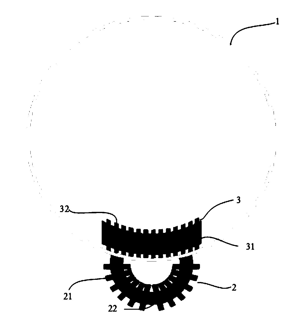
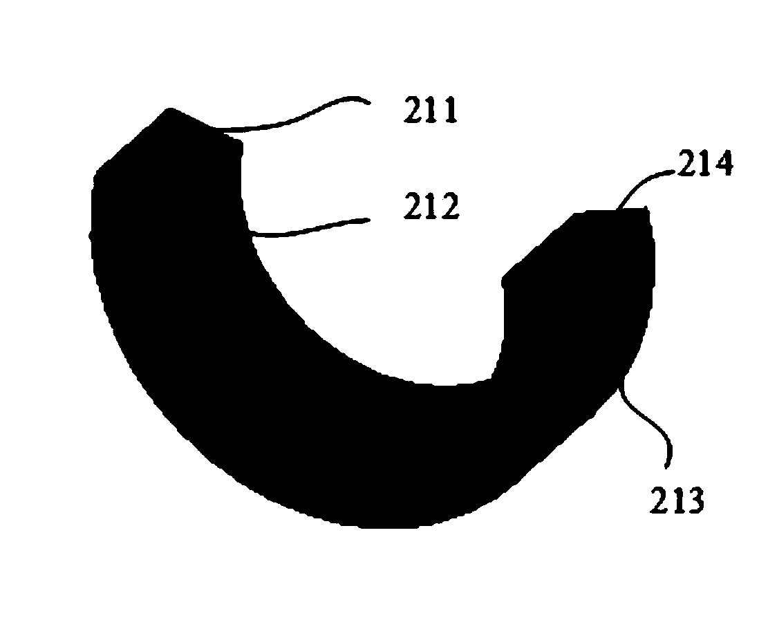
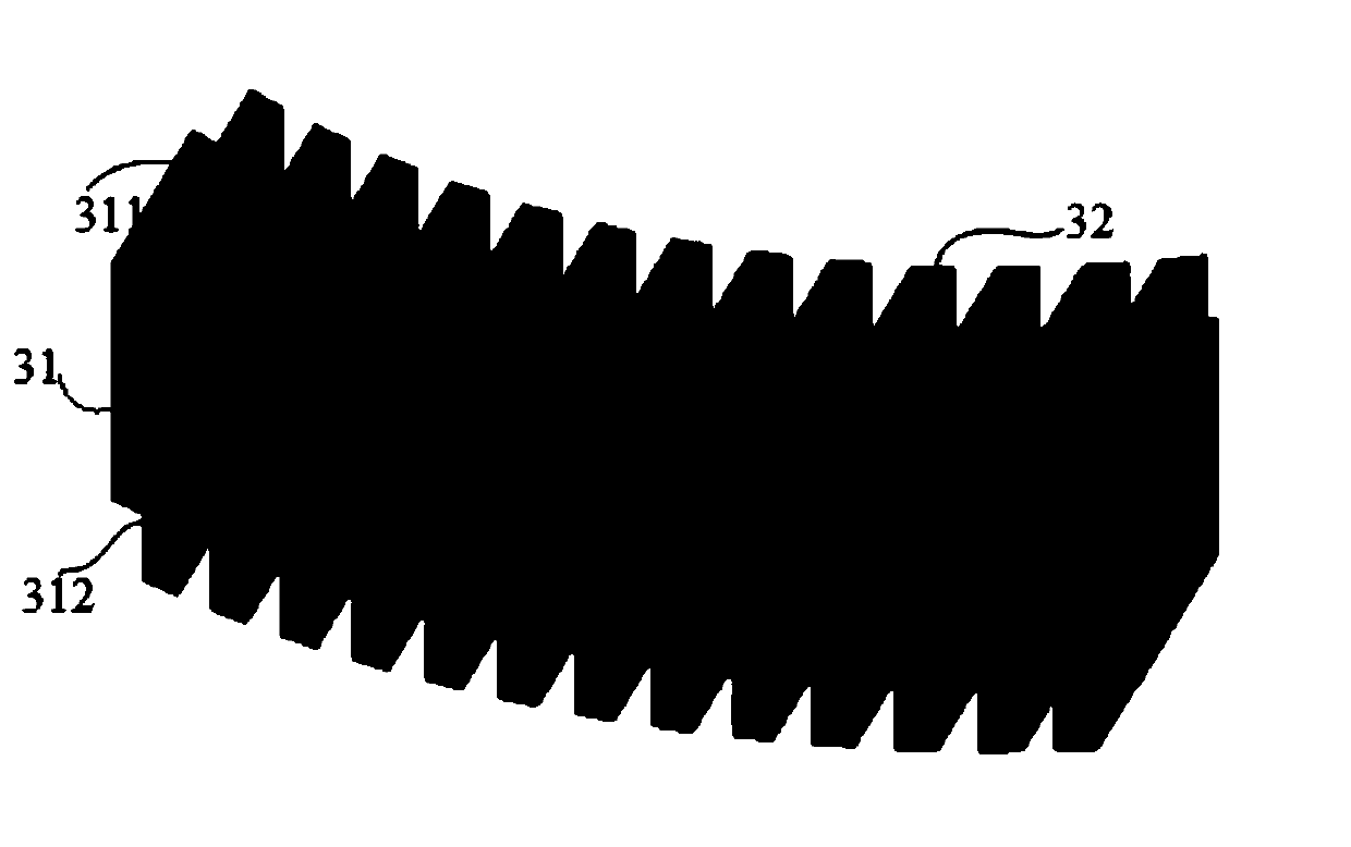
[0034] An embodiment of the present invention provides a wireless charging device for an autonomous underwater vehicle, such as Figure 1 to Figure 3 As shown, the wireless charging device is a magnetic coupling structure, and the magnetic coupling structure includes a transmitting end 2 and a receiving end 3; the transmitting end 2 has a C-shaped transmitting core 21 wound with a transmitting coil 22, and the receiving end 2 The end 3 has an arc-shaped I-type receiving core 31 wound with a receiving coil 32; the open end of the C-type transmitting core 21 forms arc cylinders 211, 214, and the arc cylinders 211, 214 are matched with the independent The arc-shaped outer surface of the autonomous underwater vehicle 1, and the outer arc-shaped surface 312 of the arc-shaped I-type receiving magnetic core 31 matches the arc-shaped inner surface of the autonomous underwater vehicle 1. In detail, such as figure 1 As shown, the transmitting end 2 is set on the charging dock, and the ...

Embodiment 2

[0059] Such as Figure 5 As shown, the embodiment of the present invention also provides an autonomous underwater vehicle system, the system includes an autonomous underwater vehicle 1, a charging dock and the autonomous underwater navigation as described in any one of the first embodiment The wireless charging device for the autonomous underwater vehicle includes a transmitting end 2 and a receiving end 3; the transmitting end 2 is set on the charging dock (not shown in the figure), and the receiving end 3 is set on the autonomous underwater vehicle. On the underwater vehicle 1, the charging dock is used to wirelessly charge the autonomous underwater vehicle through the wireless charging device.

[0060] When this embodiment of the present invention is actually implemented, reference may be made to Embodiment 1, and it has corresponding technical effects.


PUM

PropertyMeasurementUnit
Thicknessaaaaaaaaaa
Thicknessaaaaaaaaaa
Line spacingaaaaaaaaaa

Abstract

The invention discloses a wireless charging device and system for an autonomous underwater vehicle, and a coil winding method. The wireless charging device is a magnetic coupling structure including atransmitting end and a receiving end; the transmitting end is provided with a C-type transmitting magnetic core on which a transmitting coil is wound, and the receiving end has an arc surface I-typereceiving magnetic core on which a receiving coil is wound; an open end of the C-type transmitting magnetic core forms an arc cylinder surface, the arc cylinder surface is matched with an arc outer surface of the autonomous underwater vehicle, and an outer arc face of the arc surface I-type receiving magnetic core is matched with the arc inner surface of the autonomous underwater vehicle. The method includes: a step of determining wire spacing of the receiving wire coils according to the number of effective turns at the receiving end and effective length of the arc surface I-type receiving magnetic core; according to the wire spacing, the receiving wire coil is wound on the receiving end. Via the wireless charging device and system and the coil winding method, coupling between a transmitting end and a receiving end, which are misplaced, in a wireless charging device for a conventional autonomous underwater vehicle can be improved.

Description

technical field [0001] The present invention relates to the technical field of wireless charging and underwater vehicles, in particular to a wireless charging device, system and coil winding method for autonomous underwater vehicles. Background technique [0002] Autonomous underwater vehicle AUV (Autonomous Underwater Vehicle) has the advantages of high flexibility, automatic control, and high concealment, and has been widely used in the fields of marine resource exploration and seabed terrain survey. However, due to the limitations of AUV's own size and battery capacity, its load capacity and battery life are poor. Wireless charging technology can realize the charging method that AUV is completely isolated from the external environment, avoiding hidden dangers such as short circuit and electric spark, high reliability, low maintenance cost, and can complete power supply safely, reliably and efficiently. [0003] Some wireless charging devices used to charge AUVs in the pr...

Claims


Application Information

Patent Timeline
IPC IPC(8): H02J50/10H01F38/14H01F27/24H01F27/28H01F41/06H02J7/00
CPCH02J50/10H01F38/14H01F27/24H01F27/28H01F41/06Y02T10/70Y02T90/14Y02T10/7072
Inventor 蔡春伟张言语刘金泉武帅姜龙云张志鹏
Owner HARBIN INST OF TECH AT WEIHAI
Why Eureka
Try Eureka