Cuttings bed identification method and position determination method

A technology of identification method and determination method, which is applied in the field of oil and gas exploration, can solve the problems that cannot truly reflect the characteristics of downhole cuttings beds, unfavorable drilling construction, real-time identification and monitoring of cuttings beds, etc., to achieve optimal removal measures and facilitate real-time Detect and avoid the effect of prolonged stall

Active Publication Date: 2019-11-15
CHINA NAT PETROLEUM CORP CHUANQING DRILLING ENG CO LTD +1
View PDF11 Cites 2 Cited by
  • Summary
  • Abstract
  • Description
  • Claims
  • Application Information

AI Technical Summary

Problems solved by technology

[0003]At present, the identification of cuttings beds still relies on theoretical analysis and calculation, software simulation and experimental device simulation, etc. The above methods cannot realize real-time identification and identification of cuttings beds in the underground. Moreover, with the adjustment of working conditions, the results of theoretical analysis and experimental device simulation are different from the real situation, which cannot truly reflect the characteristics of the downhole cuttings bed, which is not conducive to drilling construction

Method used


Image

  • Cuttings bed identification method and position determination method
  • Cuttings bed identification method and position determination method
  • Cuttings bed identification method and position determination method

Examples


Embodiment Construction

[0023] Hereinafter, the method for identifying a cuttings bed and the method for determining a position of a cuttings bed according to the present invention will be described in detail with reference to the accompanying drawings and exemplary embodiments.

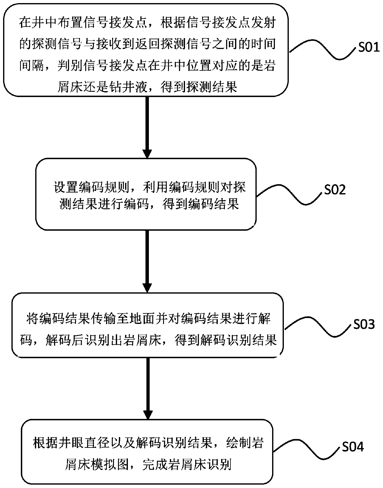
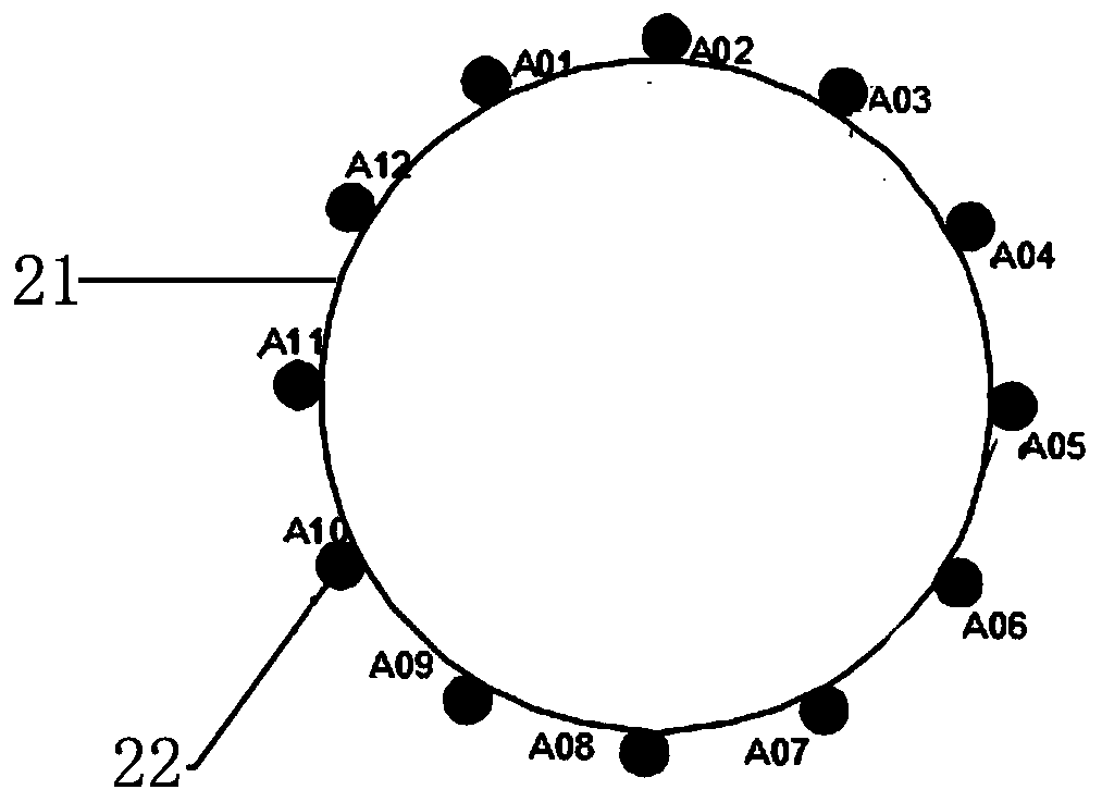
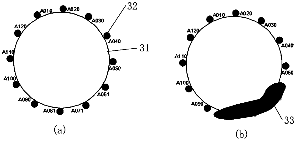
[0024] figure 1 A flowchart of a cuttings bed identification method according to an exemplary embodiment of the present invention is shown. figure 2 A schematic diagram showing the arrangement of signal receiving points along the circumferential direction of the drill string according to an exemplary embodiment of the present invention. image 3 A schematic diagram of the encoding result and a simulation diagram of the debris bed according to an exemplary embodiment of the present invention are shown, wherein, figure (a) is a schematic diagram of the encoding result, and figure (b) is a simulation diagram of the debris bed.

[0025] One aspect of the present invention provides a cuttings bed identification method, in an e...


PUM


Abstract

The invention provides a cuttings bed identification method and a position determination method. The identification method comprises the steps of: arranging a plurality of signal receiving points in awell, determining whether the position of each signal receiving point in the well corresponds to the cuttings bed or drilling liquid according to the time interval between a transmitted detection signal and a received return detection signal, and obtaining a detection result; setting a coding rule, coding the detection result by using the coding rule, and obtaining a coding result; transmitting the coding result to the ground and decoding the coding result, identifying the cuttings bed after decoding, and obtaining a decoding identification result; drawing a cuttings bed simulated diagram according to the diameter of a wellbore and the decoding identification result, and completing the cuttings bed identification. The position determination method comprises determining the position of thecuttings bed in the well according to the position of the signal receiving points. The invention can identify and monitor the condition of the underground cuttings bed in real time, and can optimizedrilling measures according to the obtained cuttings bed simulated diagram, so as to perform the continuous drilling work conveniently.

Description

technical field [0001] The invention relates to the technical field of petroleum and natural gas exploration, and more specifically, relates to a cuttings bed identification method and a position determination method. Background technique [0002] In petroleum drilling, cuttings bed is one of the most common and most harmful problems in extended-reach horizontal well drilling. The hazards of the cuttings bed are as follows: slow down the drilling speed of the machine and the construction progress, increase the construction cost, damage the drilling tools due to the increased torque, and frequent accidents such as drill sticking. With the extensive deployment of extended-reach horizontal wells for offshore and onshore shale oil and gas drilling, a series of problems caused by cuttings beds have become more and more serious. [0003] At present, the identification of cuttings beds still relies on theoretical analysis and calculation, software simulation, and experimental devi...

Claims


Application Information

Patent Timeline
Patent Type & Authority Applications(China)
IPC IPC(8): E21B47/00E21B47/12G01N29/07G01N29/024G01N23/00
CPCE21B47/00E21B47/12G01N29/07G01N29/024G01N23/00
Inventor 万夫磊邓虎陈俊斌张继川李雷明显森张林段慕白黄崇君
Owner CHINA NAT PETROLEUM CORP CHUANQING DRILLING ENG CO LTD
Why Eureka
Try Eureka