Device for automatically measuring hydrogen fluoride content and battery box containing device

An automatic measurement, hydrogen fluoride technology, applied in the direction of measuring devices, measuring electricity, measuring electrical variables, etc., can solve problems such as large economic losses, and achieve the effects of high detection, high precision, and uncomplicated structure

Pending Publication Date: 2019-11-15
北京嘉元益科技有限公司
View PDF0 Cites 0 Cited by
  • Summary
  • Abstract
  • Description
  • Claims
  • Application Information

AI Technical Summary

Problems solved by technology

Therefore, accidents caused by electrolyte leakage occur from time to time, causing huge economic losses

Method used


Image

  • Device for automatically measuring hydrogen fluoride content and battery box containing device
  • Device for automatically measuring hydrogen fluoride content and battery box containing device
  • Device for automatically measuring hydrogen fluoride content and battery box containing device

Examples


Embodiment 1

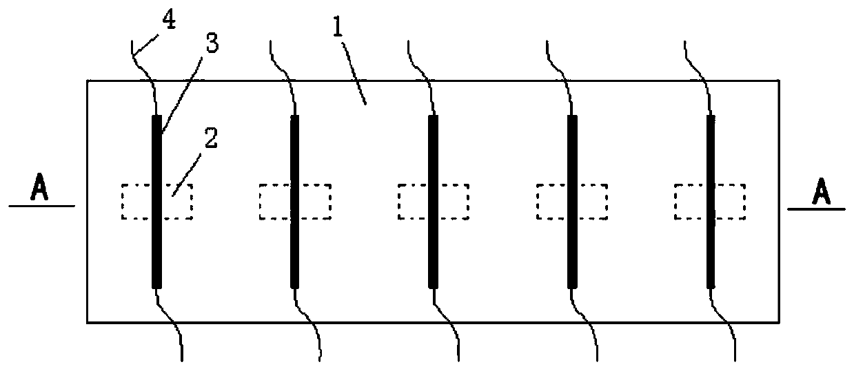
[0059] A diaphragm type device for automatically measuring the content of hydrogen fluoride. The corroded part 2 is formed by grooves on the carrier 1. Grooves of different depths correspond to corroded parts 2 of different thicknesses. The structure is simple and easy to manufacture.

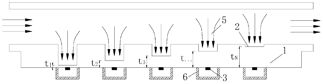
[0060] Such as Figure 2a , Figure 2b with Figure 2c As shown, one side of the carrier 1 is provided with a groove, and is in contact with the gas 5 containing hydrogen fluoride, and the part between the bottom of the groove and the other side of the carrier 1 is the etched part 2 , the distance between the groove bottom of the groove and the other side of the carrier 1 is the thickness of the corroded part 2, and the conductor plating layer 3 is attached to the position corresponding to the groove on the other side of the carrier 1 place.

[0061] The carrier 1 is made of glass, and the groove is formed by picosecond laser processing or hydrofluoric acid corrosion of the carrier 1, and a ...

Embodiment 2

[0070] A cylindrical device for automatically measuring the content of hydrogen fluoride, the corroded part 2 is a structure similar to a cylinder arranged on the carrier 1, which is equivalent to replacing the diaphragms of different thicknesses in Example 1 with cylinders of different wall thicknesses. The cylinders represent different maximum corrosion depths.

[0071] Such as Figure 3a , Figure 3b with Figure 3c As shown, the corroded part 2 is a tubular structure with uniform thickness. One end of the tubular structure is closed and fixedly connected to the carrier 1, and the other end is sealed and fixed with a cover. gas 5 contact, the conductor coating 3 is pasted on the inner side wall of the tubular structure, and is electrically connected with the control circuit 4 through the wire passing through the tubular structure, and the side wall thickness of the tubular structure is the specified The thickness of the etched part 2 is described.

[0072] The cover cover...


PUM


Abstract

The invention relates to a device for automatically measuring the hydrogen fluoride content and a battery box containing the device. The device comprises a carrier and at least one measuring unit; each measuring unit comprises a corrosion part, a conductor coating and a control circuit; the corrosion parts and the conductor coatings can be corroded by hydrogen fluoride; the corrosion parts are arranged on the carrier; one side of each corrosion part is in contact with gas containing the hydrogen fluoride; the conductor coatings are attached to the other side surfaces of the corrosion parts; the two ends of each conductor coating are electrically connected with each control circuit; the control circuits form a closed loop through the conductor coatings; after the corrosion parts are corroded and penetrated by the hydrogen fluoride, the hydrogen fluoride corrodes the conductor coatings to enable the control circuits to be turned off; and the content of the hydrogen fluoride in the gas iscalculated according to the time required for turning off the circuits and the thicknesses of the corrosion parts. According to the technical scheme, the hydrogen fluoride detection precision is high; the error is small; the content of the hydrogen fluoride can be accurately calculated; the structure is not complex; and the manufacturing cost is low.

Description

technical field [0001] The invention relates to a device for automatically measuring the content of hydrogen fluoride and a battery box containing the same, belonging to the technical field of energy storage batteries and power batteries. Background technique [0002] At present, the development momentum of lithium-ion battery-related technologies is rapid, and technological innovation is rapid. In the process of battery application, due to the high energy density of lithium-ion batteries, in the process of charging and discharging, accompanied by a variety of chemical, electrochemical reactions and material transport processes, some reactions still proceed in the case of an open circuit, these processes will If the heat is generated and cannot be completely dissipated into the environment, it will cause the accumulation of heat inside the battery. If the accumulation of heat causes a high temperature point inside the battery, it may cause thermal runaway of the battery. T...

Claims


Application Information

Patent Timeline
Patent Type & Authority Applications(China)
IPC IPC(8): G01R31/396G01R31/392
CPCG01R31/392G01R31/396
Inventor 陈川张琦
Owner 北京嘉元益科技有限公司
Why Eureka
Try Eureka