Film-like heating device

A heating device and thin-film technology, which is applied in the direction of electric heating devices, heating fuel, household heating, etc., can solve the problems of insufficient performance of the heating device, brittleness of the heating device, and undiscovered materials, etc., to achieve small power supply capacity, High heating efficiency and comfortable touch

Inactive Publication Date: 2003-04-02
PANASONIC CORP
View PDF2 Cites 0 Cited by
  • Summary
  • Abstract
  • Description
  • Claims
  • Application Information

AI Technical Summary

Problems solved by technology

However, ordinary graphite materials are difficult to use in applications that must withstand repeated twists and turns due to their poor flexibility
In particular, when a thin heat generating device is manufactured in order to improve heat generation efficiency, the heat generating device is brittle and lacks practicality.
In the case of the above-mentioned thermal insulation seat cushion, it is also required that the seat cushion can conform to the shape of the human body for soft shape change. Therefore, the heat generating device made of graphite in the past still cannot fully exert its performance.
[0009] Secondly, the existing evaporation boats are made of ceramics and the aforementioned graphite materials, which can be used at a heating temperature of about 1000°C, but are difficult to use at a high temperature of 2000-3000°C
In recent years, evaporation technology has been utilized in various fields, and it is required that this technology can be applied at higher temperatures. However, materials for evaporation boats suitable for such high-temperature evaporation processing have not yet been found.

Method used


Image

  • Film-like heating device
  • Film-like heating device
  • Film-like heating device

Examples


Embodiment 1

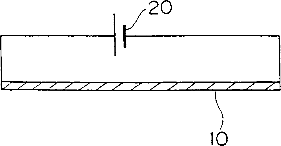
[0055] figure 1 In the shown film heating device, a DC power supply 20 is connected to both ends of a heating element 10 made of a high-crystalline graphite film through lines 22 and 22 . Also, a switch structure (not shown) for cutting off the circuit is installed in the middle of the lines 22 and 22 .

[0056] The highly crystalline graphite film 10 can be made from polyimide (DuPont, Capton H film) with a thickness of 25 μm. The graphite crystals of the highly crystalline graphite thin film 10 are oriented in the direction of the plane, and its locking property has high orientation at 20 degrees or less.

[0057] The thin film heating device of this embodiment can be assembled and used in various mechanical devices and structures. Depending on the application, the shape and pattern of the highly crystalline graphite film 10 can be freely changed.

Embodiment 2

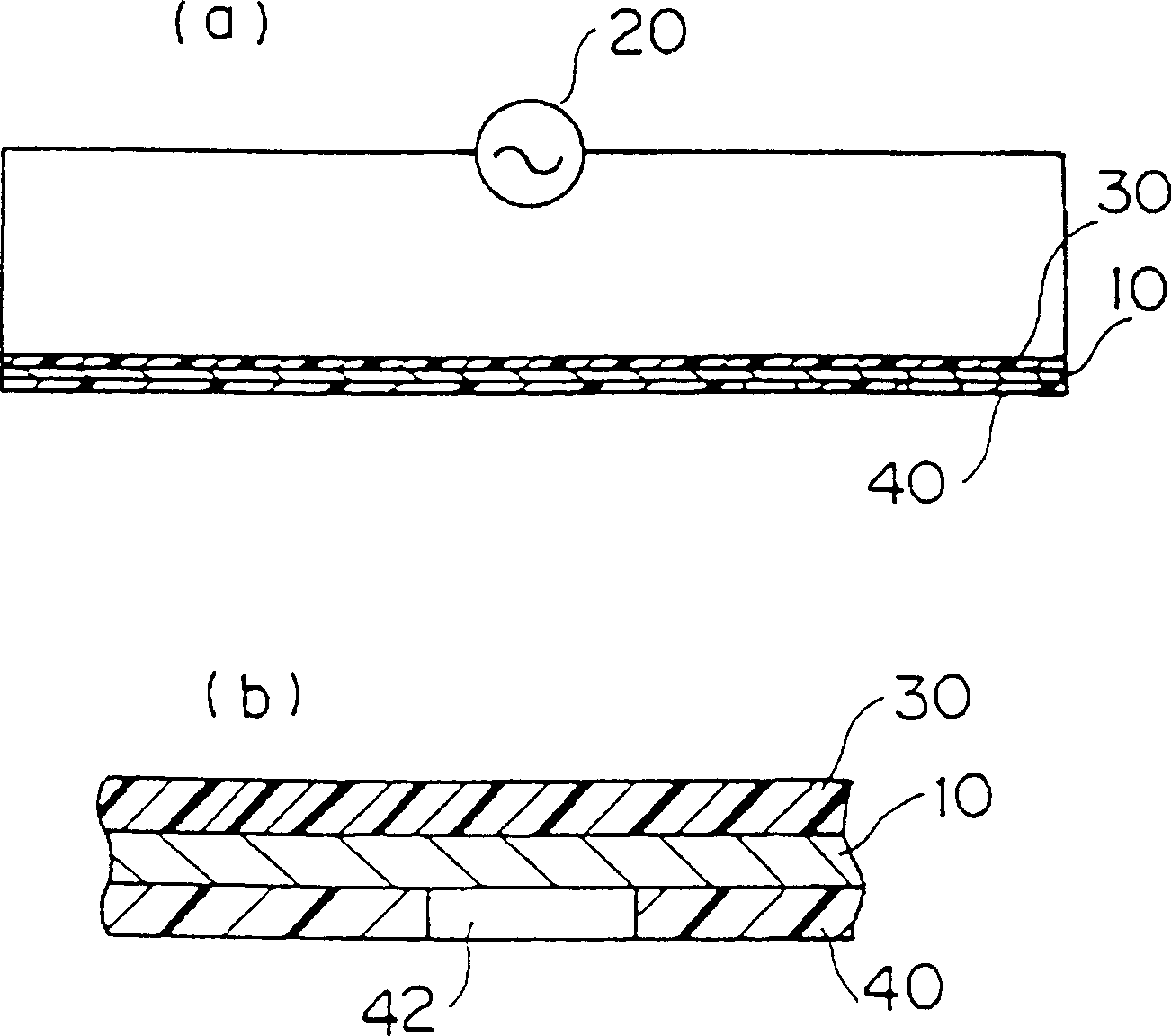
[0059] figure 2 In the film-shaped heating device shown in (a), film-shaped covering materials 30 and 40 are coated on both sides of the heating element 10 composed of the aforementioned high-crystalline graphite film. Such as figure 2 As shown in (b), the covering material 30 on one side completely covers the heat generating part 10 made of polyimide resin film. The cover material 40 on the opposite side is also made of polyimide material, and a penetration portion 42 is provided on a part of the cover material 40 .

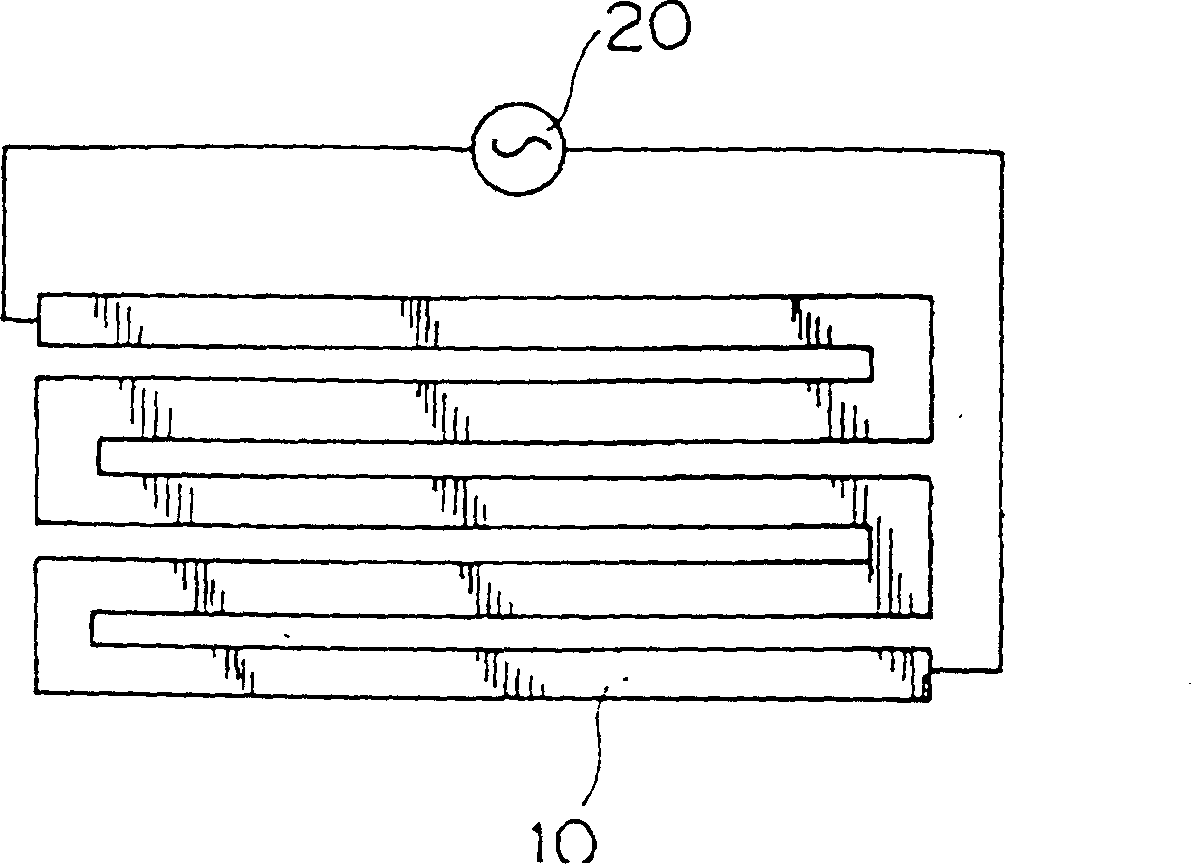
[0060] Such as image 3 As shown, the planar shape of the heat-generating component 10 is a thin strip-shaped part bent left and right. At both ends of the strip-like portion, lines 22, 22 for turning on the power source 20 are connected. The heating element 10 is obtained by cutting a planar high-crystalline graphite film.

[0061] Also, if Figure 4 As shown, a plurality of penetrating portions 42 are provided on the covering material 40 .

[0062] In...

Embodiment 4

[0070] Figure 7 The heating element 10 of the shown film heating device is composed of a plurality of strip-shaped high-crystalline graphite films 10a, 10b to form an S-shape as a whole. In this way, the entire heat generating component 10 can also be formed by combining a plurality of diaphragms.


PUM


Abstract

The invention provides a film heating devices, which include heating components 10 consisted of high crystallinity graphite film and The electricity equipment which is composed of the heating parts 10 and the energized power lines 20 and 22. The film heating devices of the invention is thin and pliable, and it is applicabled to the occasion which is repeated tortured.

Description

technical field [0001] The invention relates to a thin-film heating device. Background technique [0002] Conventionally, there is a technique of sandwiching heating components such as nickel-chromium wire or ceramic heating elements between sheet-shaped materials to form a sheet-shaped heating device. [0003] The above-mentioned sheet-shaped heating device is utilized to be packed into the seat cushion of an automobile to form a thermal insulation seat cushion. [0004] In addition, it has also been proposed that a graphite material is used as a thin film heat generating device as a thin film heat generating device. [0005] The evaporation boat is a container that holds the evaporation material during the vacuum evaporation process, and its requirement is that the evaporation material can be heated to a high temperature rapidly. [0006] A heating furnace using a heating device such as the above-mentioned nickel-chrome wire is known. Such heating furnaces are assembled...

Claims


Application Information

Patent Timeline
IPC IPC(8): H05B3/20C23C14/24H05B3/14H05B3/34
CPCH05B2203/017H05B3/145H05B2203/029H05B2203/036H05B2203/026H05B2203/004H05B3/34H05B2203/013
Inventor 光明寺大道井上孝夫西木直己池田顺治
Owner PANASONIC CORP
Why Eureka
Try Eureka