Cascadable laser traveling wave amplifier

A traveling wave amplifier and laser technology, applied in lasers, laser devices, laser parts, etc., can solve the problem of inability to quickly adjust laser amplification parameters, and achieve the effects of fast adjustment speed, free choice of magnification, and simple operation.

Pending Publication Date: 2019-11-15
SHENZHEN JPT OPTO ELECTRONICS CO LTD
View PDF0 Cites 1 Cited by
  • Summary
  • Abstract
  • Description
  • Claims
  • Application Information

AI Technical Summary

Problems solved by technology

[0003] The purpose of this application is to provide a cascadable laser traveling wave amplifier to solve the problem that the laser amplification parameters cannot be quickly adjusted in the prior art

Method used


Image

  • Cascadable laser traveling wave amplifier
  • Cascadable laser traveling wave amplifier
  • Cascadable laser traveling wave amplifier

Examples


Embodiment 1

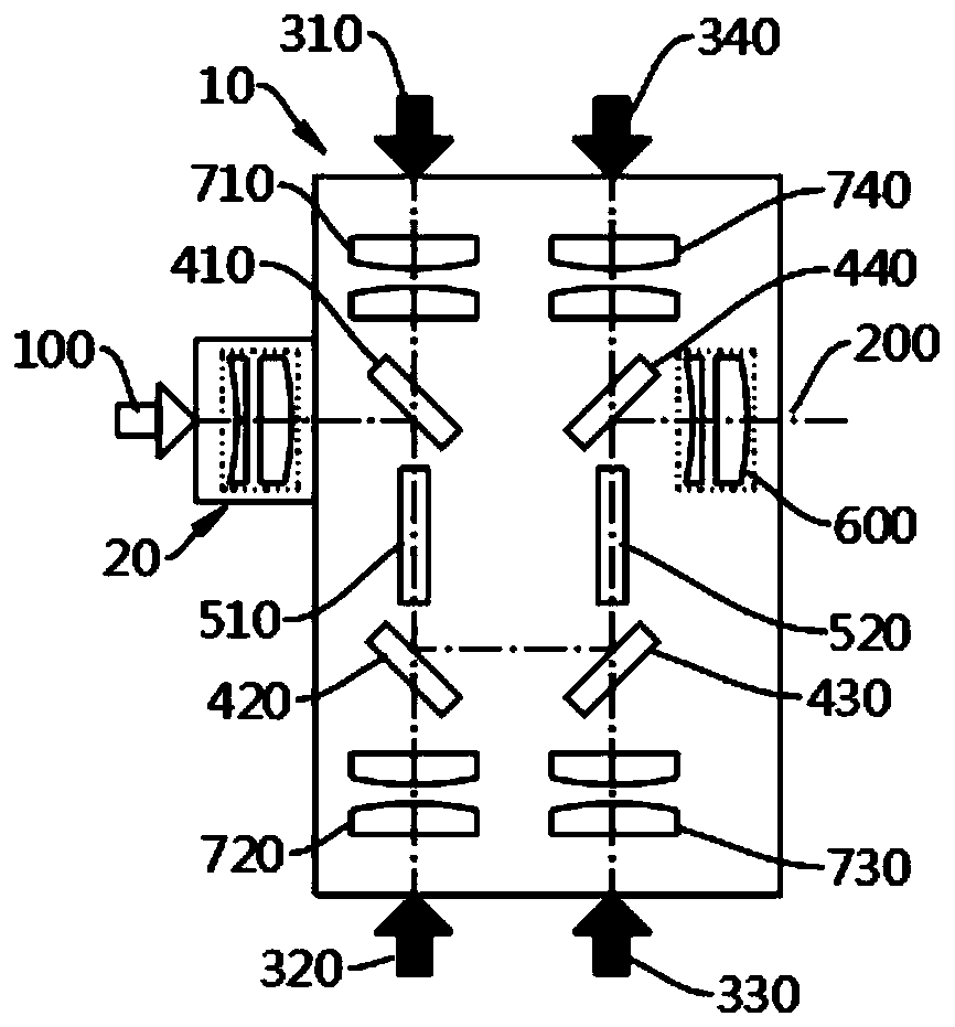
[0045] The present application provides a standardized traveling wave amplifier laser traveling wave amplifier 10, a single laser traveling wave amplifier 10 includes a seed light input end 100, a pump light input end, an amplified laser output end 200, and an amplifying optical path, the seed light input The end 100 and the amplified laser output end 200 are arranged coaxially. The seed light input from the seed light input end 100 and the pump light input from the pump light input end are amplified by the amplifying optical circuit and then output from the amplified laser output end 200.

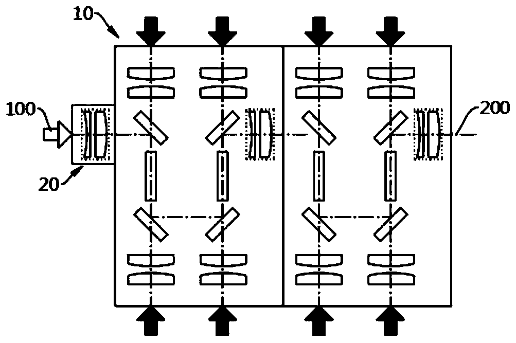
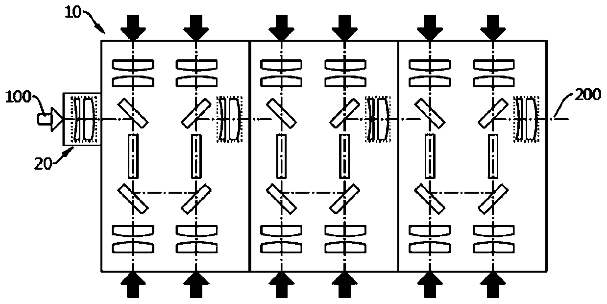
[0046] Through the above-mentioned standardized structure design, the traveling-wave amplified laser traveling-wave amplifier 10 provided in the present application can realize black-box cascade operation, forming a cascadable laser traveling-wave amplifier 10 . That is to say, multiple laser traveling wave amplifiers 10 can be connected in series in sequence, and the user can adjust the la...

Embodiment approach

[0056] The embodiment of the laser traveling wave amplifier 10 provided by the application is as follows:

[0057] (1) A single laser traveling wave amplifier 10 .

[0058] First connect the first pump light input port 310, the second pump light input port 320, the third pump light input port 330, and the fourth pump light input port 340, so that the first pump light input port 310 inputs The pumping light passes through the first half-mirror 410 and is injected into the first laser crystal 510, so that the pumping light input from the second pumping light input port 320 passes through the second half-mirror 420 and then is injected into the first laser Crystal 510, make the pump light input by the third pump light input end 330 pass through the third half mirror 430 and then inject into the second laser crystal 520, make the pump light input by the fourth pump light input end 340 pass through The second laser crystal 520 is injected into the second laser crystal 520 after pa...

Embodiment 2

[0070] In the laser traveling wave amplifier 10 in Embodiment 1, among the two end faces of each laser crystal, at least one end face is provided with a pumping light access port, so that the seed light can be amplified twice in a single laser traveling wave amplifier 10 And coaxial output.

[0071] That is to say, any one of the first pump light access end and the second pump light access end arranged at both ends of the first laser crystal 510 can be cancelled; the third pump light access end at both ends of the second laser crystal 520 Any one of the input end and the fourth pump light access end can be cancelled. Correspondingly, the canceled coupling and focusing lens group set at the pump light access end can also be canceled.

[0072] Figure 4 It is a schematic diagram of the first structure of the laser traveling wave amplifier 10 in Embodiment 2, and the first pump light access port and the first coupling and focusing lens group are omitted.

[0073] Figure 5 It...


PUM


Abstract

The invention relates to the field of laser amplification equipment. Specifically, the present invention relates to a cascadable laser traveling wave amplifier capable of being cascaded. The laser traveling wave amplifier comprises a seed light input end, a pump light input end, an amplified laser output end and an amplified light path. The seed light input end and the amplified laser output end are coaxially arranged. The seed light input from the seed light input end and pump light input from the pump light input end are amplified by the amplified light path and then output by the amplifiedlaser output end. According to the invention, the laser traveling wave amplifier forms a standardized module. Therefore, a plurality of laser traveling wave amplifiers can be cascaded. A user can amplify the laser at different multiplying powers by increasing or decreasing the number of the laser traveling wave amplifiers. The problem that an existing laser amplifier cannot quickly adjust laser amplification parameters is solved. The laser amplifier is easy to operate, high in adjustment speed and capable of freely selecting the amplification times.

Description

technical field [0001] The present application relates to the field of laser amplification equipment, in particular to a cascadable laser traveling wave amplifier. Background technique [0002] In the prior art, in order to obtain a laser with a suitable power, there are generally two schemes: direct output from the resonator and traveling wave amplification. There are certain restrictions on the direct output of the resonator. The output laser power and pulse width parameters are determined according to the shape of the resonator. Limited by the thermal lens effect of the laser crystal in the resonator, it is more difficult to obtain a laser with high power and high beam quality. limit. Traveling wave amplification is to amplify the seed light by adding an amplification stage to the seed source, so that a laser output with high laser intensity and similar parameters to the seed light can be obtained. Regardless of the resonator output or the amplified output, the existing...

Claims


Application Information

Patent Timeline
IPC IPC(8): H01S3/23
CPCH01S3/2316
Inventor 任戬刘猛刘健黄治家
Owner SHENZHEN JPT OPTO ELECTRONICS CO LTD
Why Eureka
Try Eureka