Steel ladle top slag modification method suitable for low-carbon and ultra-low-carbon steel

A technology of ultra-low carbon steel and ladle top slag, which is applied in the field of low carbon, ladle top slag modification, and ultra-low carbon steel ladle top slag modification, which can solve serious environmental pollution, change the oxidation of ladle top slag, and Potential safety hazards and other issues, to meet environmental protection requirements, improve the cleanliness index of molten steel, and change the effect of oxidation

Pending Publication Date: 2019-11-19
MAANSHAN IRON & STEEL CO LTD
View PDF4 Cites 5 Cited by
  • Summary
  • Abstract
  • Description
  • Claims
  • Application Information

AI Technical Summary

Problems solved by technology

[0011] Aiming at the technical problems of major safety hazards, serious environmental pollution and poor modification effect in the ladle top slag modification method mentioned in the background technology, the purpose of the present invention is to provide a method suitable for low-carbon and ultra-low-carbon Steel ladle top slag modification method, this modification method can significantly change the oxidation of ladle top slag, the cleanliness index of molten steel has been improved to varying degrees, and the modification process does not pollute the site environment, which can meet environmental protection requirements

Method used


Image

  • Steel ladle top slag modification method suitable for low-carbon and ultra-low-carbon steel
  • Steel ladle top slag modification method suitable for low-carbon and ultra-low-carbon steel
  • Steel ladle top slag modification method suitable for low-carbon and ultra-low-carbon steel

Examples


Embodiment

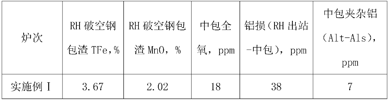
[0040] Embodiment Ⅰ: steel type: IF steel DC06; actual molten steel amount: 310 tons

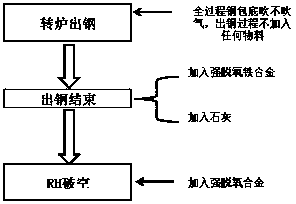
[0041] (1) During the tapping process of the converter, argon is not blown into the ladle, and no deoxidizer and slagging material are added;

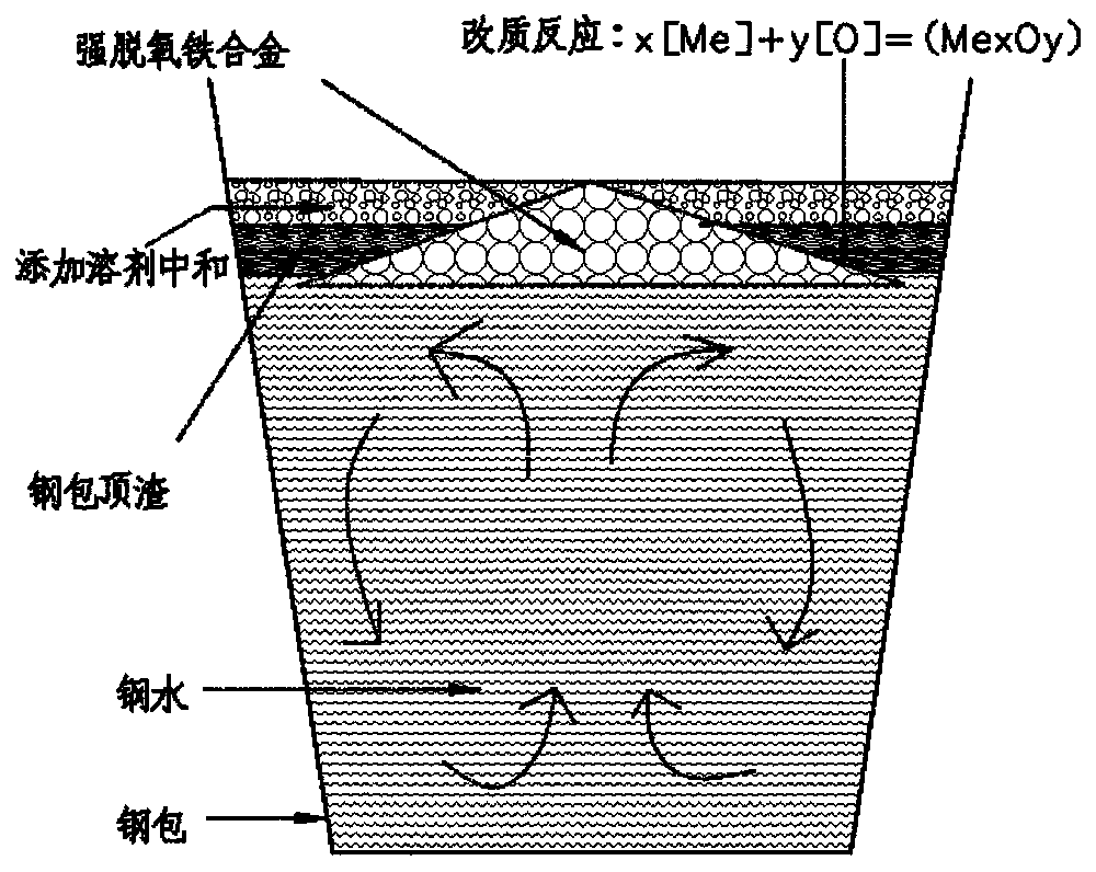
[0042] (2), after the completion of tapping, add a specific gravity of 5.75g / cm into the ladle 3 Aluminum and iron 934kg. There is no obvious smoke and dust emission during and after the addition of aluminum and iron;

[0043] (3), after tapping finished adding aluminum and iron, add lime 1408kg in ladle. There is no obvious smoke and dust emission during and after lime addition;

[0044] (4) When the RH cycle is completed, 20kg of aluminum particles are added to the molten steel in the vacuum chamber just before the molten steel drops out of the vacuum chamber, and 35kg of aluminum particles are added to the slag surface of the ladle after the hole is broken. There is no obvious smoke and dust emission during and after the addition of aluminum p...


PUM


Abstract

The invention discloses a steel ladle top slag modification method suitable for low-carbon and ultra-low-carbon steel. The steel ladle top slag modification method comprises the following steps of 1,not blowing argon into a steel ladle in a converter tapping process without adding any deoxidizing agent or slagging material; 2, adding a strong deoxidation iron alloy with the specific gravity between that of top slag and that of molten steel into the steel ladle after tapping is completed, wherein the adding amount of the strong deoxidation iron alloy is determined according to the actual molten steel amount in the steel ladle; 3, adding a lime flux into the steel ladle after the strong deoxidation iron alloy is added, wherein the lime adding amount is determined according to the actual molten steel amount in the steel ladle; 4, adding a strong deoxidation alloy into molten steel in a vacuum chamber when RH circulating vacuum breaking is finished and before the molten steel drops and just starts to flow out of the vacuum chamber, wherein the adding amount of the strong deoxidation alloy is determined according to the actual molten steel amount; and 5, performing RH decarburization,deoxidation and alloying operation methods which are the same as conventional methods currently in effect in a steel plant. By applying the method, the ladle top slag oxidability can be remarkably changed, the cleanliness indexes of the molten steel are improved to different degrees, the field environment is not polluted in the modification process, and environment protection requirements can be met.

Description

technical field [0001] The invention belongs to the technical field of steelmaking, and relates to a ladle top slag upgrading method, in particular to a ladle top slag upgrading method suitable for low-carbon and ultra-low carbon steel. Background technique [0002] The low-carbon and ultra-low-carbon steels in the "converter-RH-continuous casting" process path are generally aluminum-killed steels with relatively high aluminum content, and the acid-soluble aluminum content in molten steel is relatively high. During the process, especially in the later stage of pouring, the oxygen in the ladle slag will continuously react with the acid-soluble aluminum in the molten steel to form Al which is not conducive to the quality of the molten steel. 2 o 3 Inclusions lead to a decrease in the cleanliness of molten steel. A large number of experiments and industrial production results have confirmed that the iron oxide content in the ladle top slag is directly related to the aluminum ...

Claims


Application Information

Patent Timeline
IPC IPC(8): C21C7/076C21C7/06C21C7/10
CPCC21C7/076C21C7/06C21C7/10Y02P10/20
Inventor 乌力平李应江徐小伟邓勇王泉单永刚
Owner MAANSHAN IRON & STEEL CO LTD
Why Eureka
Try Eureka