Multi-rotating-shaft evaporator capable of accurately and quantitatively concentrating plurality of samples in one time
A quantitative concentration, rotating shaft technology, applied in the direction of distillation, distillation separation, chemical instruments and methods in rotating containers, can solve the problems of low efficiency, small evaporation area of parallel evaporators, etc., to facilitate installation and eliminate steric hindrance , cost saving effect
- Summary
- Abstract
- Description
- Claims
- Application Information
AI Technical Summary
Problems solved by technology
Method used
Image

Examples
Embodiment 1
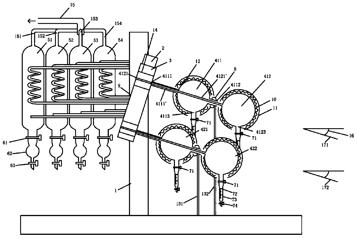
[0069] see figure 1 As shown, the multi-rotary shaft evaporator capable of accurately quantitatively concentrating multiple samples described in this embodiment includes: a bracket 1 on which a rotating motor 2 is fixed, and the rotating motor 2 drives two The distillation flask on the bar rotation axis 171,172 rotates (the rotary evaporator of the present invention is also provided with a control panel and components for controlling the rotating speed of the rotating motor and the heating temperature, not shown in the figure), and the rotation can be unidirectional or The two directions are carried out alternately, and the rotation of the two rotation axes 171 and 172 driven by the rotating motor 2 can be completed by crawlers, chains or gears in the transmission body 3;
[0070] The two rotation axes 171, 172 have a downward angle with the horizontal plane, which is 15 degrees;
[0071] One end of the transmission body 3 is fixed with a detachable distillation bottle group ...
Embodiment 2
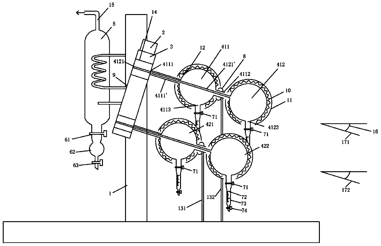
[0102] like figure 2 As shown, different from Example 1, the evaporated gas in the four distillation flasks first passes through respective steam pipes, then passes through respective condensation pipes, and then enters a common condenser 5 after passing through the main pipe of the condensation pipes. Condensation is collected in a collector 6.
Embodiment 3
[0104] Different from Example 1, the number of distillation bottles contained in the distillation bottle group can be 2 or 3 or 5 or more.
PUM
 Abstract
Description
Claims
Application Information
 - R&D
- Intellectual Property
- Life Sciences
- Materials
- Tech Scout
- Unparalleled Data Quality
- Higher Quality Content
- 60% Fewer Hallucinations
Browse by: Latest US Patents, China's latest patents, Technical Efficacy Thesaurus, Application Domain, Technology Topic, Popular Technical Reports.
© 2025 PatSnap. All rights reserved.Legal|Privacy policy|Modern Slavery Act Transparency Statement|Sitemap|About US| Contact US: help@patsnap.com