Aspherical lens adjustable annular light spot fixed magnification cutting device

A ring-shaped spot and aspherical mirror technology, which is applied in laser welding equipment, welding equipment, metal processing equipment, etc., can solve the problems of unfavorable process optimization of plates with different thicknesses, non-adjustable diameter, and difficult mirror surface processing, etc., and achieve mechanical design and control. The difficulty is controllable, the effect of ensuring the processing of the lens and increasing the cutting speed

Inactive Publication Date: 2019-11-22
SHANGHAI EMPOWER AUTOMATION TECH CO LTD
View PDF0 Cites 2 Cited by
  • Summary
  • Abstract
  • Description
  • Claims
  • Application Information

AI Technical Summary

Problems solved by technology

The single-piece axicon lens cannot realize the adjustable annular spot, which is not conducive to the process optimization of plates with different thicknesses; the HighYAG free-form surface lens group needs to be adjusted with a double-piece free-form surface lens group, and additionally requires the movement of the collimator or focusing lens to compensate for the focus The position increases the difficulty of mechanical design and control, and the mirror surface processing is very difficult; the Precitec micro-lens group can realize the adjustment of the energy ratio from a solid spot to a fixed-diameter annular spot, and there is also the problem of non-adjustable diameter, while the single-chip micro-lens solution is reduced. The number of lenses reduces the cost, but the diameter cannot be adjusted, the focus spot is circular, and it is impossible to perforate, so the lens needs to be constantly switched during the cutting process

Method used


Image

  • Aspherical lens adjustable annular light spot fixed magnification cutting device
  • Aspherical lens adjustable annular light spot fixed magnification cutting device
  • Aspherical lens adjustable annular light spot fixed magnification cutting device

Examples


Embodiment Construction

[0024] The following will clearly and completely describe the technical solutions in the embodiments of the present invention with reference to the accompanying drawings in the embodiments of the present invention. Obviously, the described embodiments are only some, not all, embodiments of the present invention. Based on the embodiments of the present invention, all other embodiments obtained by persons of ordinary skill in the art without making creative efforts belong to the protection scope of the present invention.

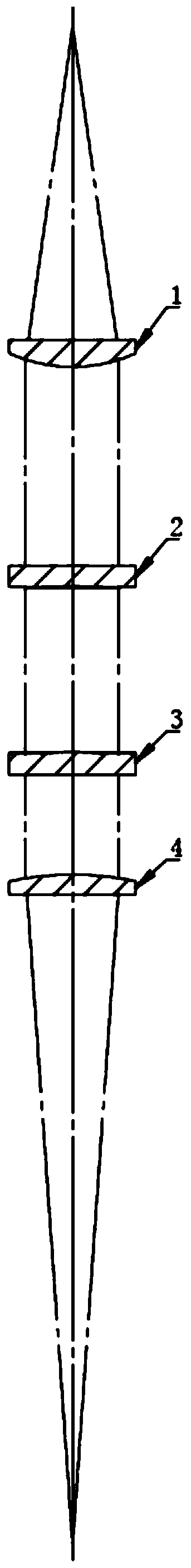
[0025] see figure 1 , the present invention provides a technical solution: a fixed-magnification cutting solution based on an aspheric mirror adjustable annular spot, including an aspheric collimator lens 1, a first curved axicon lens 2, a second curved axicon lens 3 and an aspheric focusing lens 4. Among them, the aspheric collimating lens 1, the first curved axicon lens 2, the second curved axicon lens 3 and the aspheric focusing lens 4 are coaxial with the...


PUM


Abstract

The invention discloses an aspherical lens adjustable annular light spot fixed magnification cutting device. The device comprises an aspherical collimating lens, a first curved surface conical lens, asecond curved surface conical lens and an aspheric focusing lens, wherein the aspherical collimating lens, the first curved surface conical lens, the second curved surface conical lens and the aspheric focusing lens central axis are coaxial; the aspheric collimating lens and the aspheric focusing lens form a fixed magnification magnifying lens group; and the first curved surface conical lens andthe second curved surface conical lens form an annular adjustable lens group. According to the device, the structural design is novel, the diameter of the focusing focal point solid light spot to an annular light spot and the annular light spot is continuously adjustable; meanwhile, the annular energy distribution of the corresponding off-focal light beam section is realized on the basis of the laser cutting process, so that the cutting speed, the cross section quality and the cutting thickness of the plate are improved; and the device is suitable for laser cutting and application of a kilowatt-watt-grade high-power fiber laser, especially for the cutting application of medium and thick plates in a continuous fiber laser with the fiber core diameter of 50 microns or more.

Description

technical field [0001] The invention relates to the technical field of fiber laser cutting, in particular to a fixed-magnification cutting device for an adjustable annular spot based on an aspheric mirror. Background technique [0002] Due to the advantages of high electro-optical conversion efficiency, good fiber flexibility, high coupling efficiency, and good beam quality, as well as the emergence of high-power lasers, fiber lasers have made their market share increasingly prominent. At present, fiber-coupled output lasers of kilowatt level are quite popular. Watt-level lasers are gradually released to the market, making fiber laser processing more and more common. [0003] The laser cutting application of fiber laser covers various metal processing markets such as stainless steel, carbon steel, aluminum, copper, etc. With the increase of laser power, the cutting thickness of plates of different materials becomes thicker. [0004] As we all know, although the conventional...

Claims


Application Information

Patent Timeline
IPC IPC(8): B23K26/38B23K26/70B23K26/064B23K26/073
CPCB23K26/064B23K26/0648B23K26/073B23K26/0734B23K26/38B23K26/70B23K26/702
Inventor 邵华江李思佳
Owner SHANGHAI EMPOWER AUTOMATION TECH CO LTD
Why Eureka
Try Eureka