Combustible solid waste pyrolysis device and pyrolysis method

A solid waste and pyrolysis technology, which is applied in the direction of direct heating dry distillation, special form dry distillation, petroleum industry, etc., can solve the difficulty of pyrolysis control of combustible solid waste, large fluctuation range of solid waste composition, composition ratio changes, etc. problems, to achieve the effects of easy large-scale continuous production, accurate control of solid circulation flux, and avoiding high oxidation and deformation

Inactive Publication Date: 2019-11-22
SOUTHEAST UNIV
View PDF6 Cites 2 Cited by
  • Summary
  • Abstract
  • Description
  • Claims
  • Application Information

AI Technical Summary

Problems solved by technology

[0004] However, the generation of solid waste has certain regional and seasonal characteristics, and the composition of solid waste fluctuates widely, which makes it difficult to control the pyrolysis of combustible solid waste in practical industrial applications. At the same time, the proportion of each component of the product changes. also more obvious
The double fluidized bed system can better solve the appeal problem. However, when the double fluidized bed is used for pyrolysis combustion, the control of high-temperature circulating materials between the two furnaces is the key. The existing technology adopts pneumatic conveying or high-temperature Jiaolong mechanical conveying, etc. method, the system is complicated and the reliability is poor. To realize the circulation flow of a large amount of high-temperature circulating materials between the two furnaces, and to prevent the pyrolysis oil gas and flue gas from colluding between the two furnaces, the existing technology is difficult to solve

Method used


Image

  • Combustible solid waste pyrolysis device and pyrolysis method

Examples


Embodiment Construction

[0026] The technical solution of the present invention will be further described below in conjunction with the accompanying drawings.

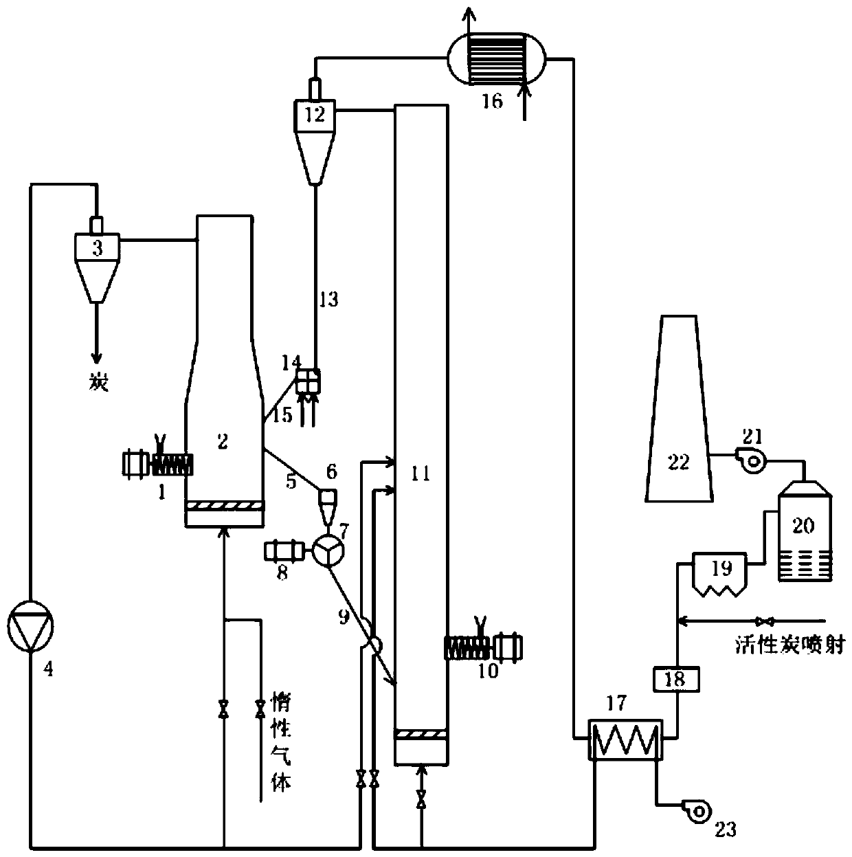
[0027] A combustible solid waste pyrolysis device of the present invention, such as figure 1 , the device uses alternating circulation double fluidized bed, including fluidized bed combustion reactor and fluidized bed pyrolysis reactor.

[0028] The upper outlet of the fluidized bed pyrolysis reactor 2 is connected to the pyrolysis reactor cyclone separator 3, and the solid carbon is directly collected by the pyrolysis reactor cyclone separator 3, and the gas is connected to the circulating fan 4; the fluidized bed pyrolysis reactor The middle part is provided with a pyrolysis reactor overflow inclined pipe 5 connected to the pyrolysis reactor buffer bin 6, and then sent to the pyrolysis reactor star-shaped feeder 7; the star-shaped feeder 7 passes through the combustion reactor to return the inclined pipe 9 is connected to the fluidized bed ...


PUM

PropertyMeasurementUnit
particle sizeaaaaaaaaaa
particle diameteraaaaaaaaaa

Abstract

The invention discloses a combustible solid waste pyrolysis device and a pyrolysis method. The pyrolysis device comprises a fluidized bed pyrolysis reactor and a fluidized bed combustion reactor whichadopt heat carrier bed material interactive circulation. Combustible solid waste fuel is pyrolyzed in the fluidized bed pyrolysis reactor, and a heat carrier bed material overflows and is sent to thecombustion reactor through a star-shaped return feeder; the heat carrier bed material is heated again by utilizing heat released by pyrolysis oil gas combustion in the combustion reactor; and the heated heat carrier bed material enters the pyrolysis reactor again through a fluidized bed return feeder. Heat generated by combustion is transmitted to a pyrolysis process by utilizing interactive circulation of the heat carrier bed material between the two reactors, so that the problem of non-uniform temperature in reactors caused by heat transfer of conventional reactors is solved; the star-shaped return feeder for pyrolysis material returning achieves a good sealing effect, the fluidized bed material return feeder for combustion material returning avoids high oxidation and deformation of mechanical moving parts, and meanwhile the solid circulation flux can be controlled.

Description

technical field [0001] The invention relates to a combustible solid waste pyrolysis device and a pyrolysis method, belonging to the thermal treatment and reuse technology of combustible solid waste. Background technique [0002] A considerable amount of solid waste is generated in our country's production and life every year, including agricultural and forestry waste, municipal solid waste, municipal sludge, etc. The treatment and efficient utilization of these solid wastes is of great significance. [0003] Solid waste treatment has a long history. In the early days, because of the small size of the city, small-scale solid wastes were buried or piled nearby. With the development of society, more and more solid wastes are produced, and environmental protection requirements have become More stringent, solid waste treatment technology continues to develop, and has achieved remarkable results in reduction, recycling and harmlessness. Currently, more representative treatment tec...

Claims


Application Information

Patent Timeline
Patent Type & Authority Applications(China)
IPC IPC(8): C10B53/00C10B57/00C10B49/22
CPCC10B49/22C10B53/00C10B57/00
Inventor 黄亚继胡华军樊聪慧戚二兵丁守一金保昇
Owner SOUTHEAST UNIV
Why Eureka
Try Eureka