Blast furnace gas dechlorination and desulfurization system and process

A blast furnace gas and desulfurization system technology, applied in gas dust removal, petroleum industry, combustible gas purification, etc., can solve problems such as hidden dangers of safety production, increase production costs of enterprises, corrosion and perforation, etc., so as to reduce production safety risks and operating costs. The effect of saving enterprise funds and enterprise land and prolonging the service life

Inactive Publication Date: 2019-11-22
MAANSHAN BAOTIAN HEAVY IND MACHINERY
View PDF1 Cites 10 Cited by
  • Summary
  • Abstract
  • Description
  • Claims
  • Application Information

AI Technical Summary

Problems solved by technology

[0005] The current gas desulfurization / desulfurization equipment is mainly to remove sulfur, namely H, from coke oven gas or artificial gas. 2 S, the sulfur in blast furnace gas is mainly COS, and the desulfurization of blast furnace gas is mainly to remove COS. The existing gas desulfurization process cannot remove COS in blast furnace gas, so the existing gas desulfurization process cannot meet the requirements of blast furnace gas desulfurization. Require
[0006] In addition, with the popularization of blast furnace gas dry dedusting, most domestic iron and steel enterprises adopt dry dedusting for blast furnace gas. Chloride ions in dry dedusting blast furnace gas exceed the standard, resulting in serious corrosion of TRT blades and gas pipe network. The gas pipelines of iron and steel enterprises treated with dechlorination are generally used for about 3 years, and all of them have different degrees of corrosion and perforation. Generally, the pipelines need to be replaced after about 6 years, which brings great safety hazards to the safe production of enterprises.
Since blast furnace gas pipelines generally have no spare pipelines or cut-off valves in the factory mains, replacing the mains often requires the company to stop production for replacement, seriously affecting the normal production of iron and steel companies, causing huge safety hazards, and replacing the pipelines also greatly increases the production cost of the company

Method used


Image

  • Blast furnace gas dechlorination and desulfurization system and process
  • Blast furnace gas dechlorination and desulfurization system and process

Examples


Embodiment Construction

[0024] The following will clearly and completely describe the technical solutions in the embodiments of the present invention with reference to the accompanying drawings in the embodiments of the present invention. Obviously, the described embodiments are only some, not all, embodiments of the present invention. Based on the embodiments of the present invention, all other embodiments obtained by persons of ordinary skill in the art without making creative efforts belong to the protection scope of the present invention.

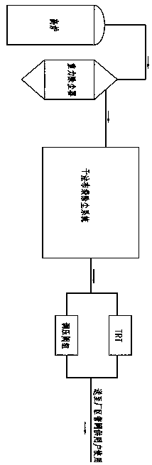
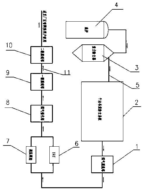
[0025] see figure 2 The present invention provides a technical solution: a blast furnace gas dechlorination and desulfurization system, comprising a blast furnace gas dechlorination tower 1 and a blast furnace gas desulfurization system, the front end of the blast furnace gas dechlorination tower 1 is provided with a dry bag dust removal system 2, the The front end of the dry bag dust removal system 2 is provided with a gravity dust collector 3, the gravity d...


PUM


Abstract

The invention discloses a blast furnace gas dechlorination and desulfurization system and process. The system comprises a blast furnace gas dechlorination tower and a blast furnace gas desulfurizationsystem, blast furnace gas passes through a gravity dust collector and a dry bag-type dust collector and then is conveyed into a blast furnace gas dechlorination tower, the blast furnace gas dechlorinated by the dechlorination tower enters a blast furnace gas desulfurization system through a TRT or a pressure regulating valve bank, a catalytic tower in the desulfurization system catalyzes COS in the blast furnace gas, and the COS is converted into H2S; the blast furnace gas treated by the catalytic tower is conveyed to a dechlorination tower of the blast furnace gas dechlorination system, andH2S in the blast furnace gas is desulfurized by the blast furnace gas dechlorination tower; and the treated blast furnace gas is transmitted to a blast furnace gas main pipe of a factory through a gaspipe network for each user to use. The blast furnace gas dechlorination and desulfurization treatment process is integrated, the problem that SO2 in flue gas exceeds the standard after the blast furnace gas is combusted can be effectively solved, and in addition, corrosion of TRT blades and corrosion of blast furnace gas pipelines are greatly delayed through the dechlorinated blast furnace gas.

Description

technical field [0001] The invention relates to the technical field of blast furnace waste gas treatment, in particular to a blast furnace gas dechlorination and desulfurization system and process. Background technique [0002] Blast furnace gas is a by-product combustible gas in the blast furnace production process. It has a large output and is widely used. It can be used as fuel for blast furnaces in power plants, hot blast stoves in rolling mills, and heating furnaces in ironworks. The main components of blast furnace gas are CO, CO 2 , N 2 , also contains a small amount of COS, H 2 S, Cl - , dust, etc. [0003] At present, the blast furnace gas produced by the blast furnace is one of the main fuels for the entire iron and steel company, and is often used as fuel for blast furnaces in power plants, hot blast stoves in rolling mills, and heating furnaces in ironworks. [0004] Since there is no blast furnace gas desulfurization device in use in China at present, SO in...

Claims


Application Information

Patent Timeline
Patent Type & Authority Applications(China)
IPC IPC(8): C10K1/00C10K1/02C10K1/12C10K1/34
CPCC10K1/003C10K1/004C10K1/02C10K1/024C10K1/122C10K1/34
Inventor 任长浩
Owner MAANSHAN BAOTIAN HEAVY IND MACHINERY
Why Eureka
Try Eureka