
Method and device for improving continuous casting flaw detection qualification rate

A pass rate, continuous casting technology, applied in the field of metallurgy, can solve the problems of unqualified flaw detection, inability to quickly identify the pass rate of continuous casting billet flaw detection, aggravate the central segregation and banded structure of continuous casting billet, etc., to ensure internal quality, improve The pass rate of flaw detection and the effect of reducing inclusion content

Active Publication Date: 2019-11-22
LIANFENG STEEL (ZHANGJIAGANG) CO LTD
View PDF14 Cites 11 Cited by
  • Summary
  • Abstract
  • Description
  • Claims
  • Application Information

AI Technical Summary

Problems solved by technology

[0005] The embodiment of this specification provides a method and device for improving the pass rate of continuous casting flaw detection, which solves the problems in the prior art that large inclusions and microcracks are easy to appear in the continuous casting slab during the rolling process, and it is easy to aggravate the cracks in the center of the continuous casting slab. Segregation and banded structure lead to unqualified flaw detection, and the technical problem that the pass rate of flaw detection of continuous casting slabs cannot be quickly identified, so as to improve the pass rate of flaw detection of continuous casting slabs, reduce inclusion content, and ensure the internal quality of continuous casting slabs. The technical effect of reducing production costs

Method used


Image

  • Method and device for improving continuous casting flaw detection qualification rate
  • Method and device for improving continuous casting flaw detection qualification rate
  • Method and device for improving continuous casting flaw detection qualification rate

Examples


Embodiment 1

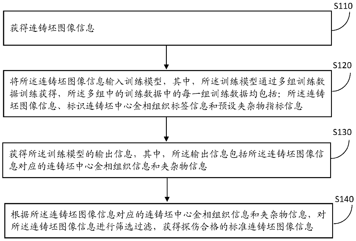
[0051] figure 1 It is a schematic flowchart of a method for improving the qualified rate of continuous casting flaw detection in the embodiment of the present invention. Such as figure 1 shown. The method is applied to a device for improving the qualified rate of continuous casting flaw detection. The processing device for improving the qualified rate of continuous casting flaw detection includes an input device and a display device. The input device has a picture input module, a picture processing module, and a memory inside. , a signal input module, the input device can be connected to the equipment that generates output signals such as energy spectrum scanners, scanning electron microscopes, etc., the display device is connected to the input device, and the energy spectrum scanner, scanning electron microscope, etc. The image processed by the input device is displayed on a device such as a display screen. The method includes steps S101-S104.

[0052] S101: Obtain image ...

Embodiment 2

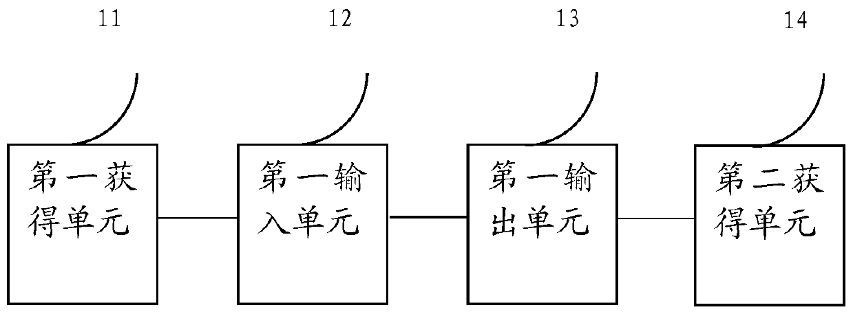
[0066] Based on the same inventive concept as a method for improving the pass rate of continuous casting flaw detection in the foregoing embodiments, the present invention also provides a device for improving the pass rate of continuous casting flaw detection, such as figure 2 shown, including:

[0067] The first obtaining unit 11 is used to obtain continuous casting slab image information;

[0068] The first input unit 12 is used to input the image information of the continuous casting slab into the training model, wherein the training model is obtained by training multiple sets of training data, and each set of training data in the multiple sets of training data is Including: the continuous casting slab image information, label information identifying the metallographic structure of the continuous casting slab center and preset inclusion index information;

[0069] The first output unit 13 is configured to obtain output information of the training model, wherein the output...

Embodiment 3

[0093] Based on the same inventive concept as the method for improving the qualified rate of continuous casting flaw detection in the first embodiment, the present invention also provides a computer-readable storage medium on which a computer program is stored, and when the program is executed by a processor, the foregoing A step in any method of the method for improving the qualified rate of continuous casting flaw detection.

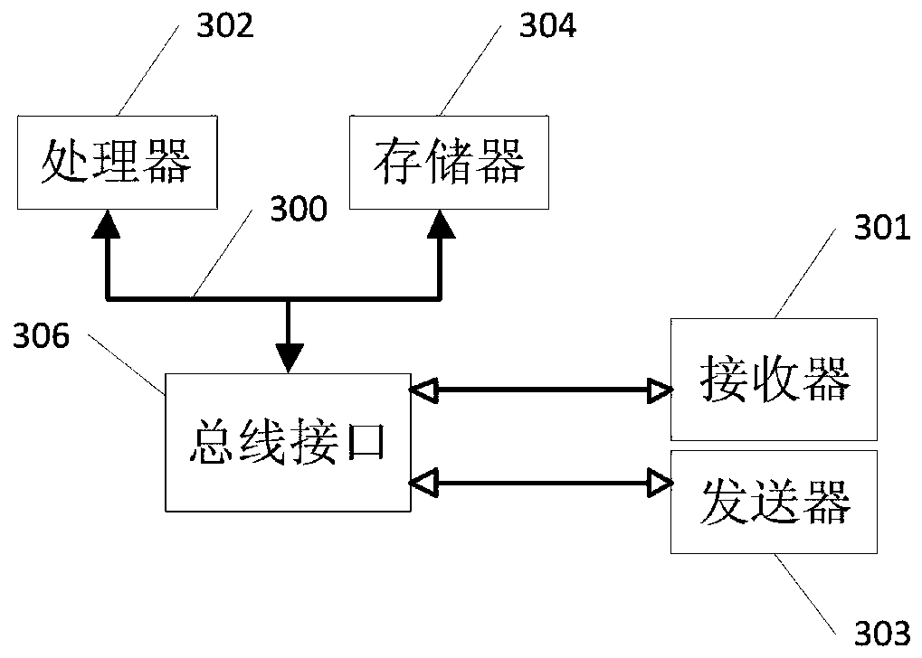
[0094] Among them, in image 3 In, bus architecture (represented by bus 300), bus 300 may include any number of interconnected buses and bridges, bus 300 will include one or more processors represented by processor 302 and various types of memory represented by memory 304 circuits linked together. The bus 300 may also link together various other circuits, such as peripherals, voltage regulators, and power management circuits, etc., which are well known in the art and thus will not be further described herein. The bus interface 306 provides an interfa...


PUM


Abstract

The embodiment of the invention provides a method and device for improving the continuous casting flaw detection qualification rate. The method comprises the steps that obtained continuous casting billet image information is input into a training model, the training model is obtained through training of multiple sets of training data, and each set of training data in the multiple sets of trainingdata comprises the continuous casting billet image information, identification continuous casting billet center metallographic structure label information and preset inclusion index information; output information of the training model is obtained, and the output information comprises continuous casting billet center metallographic structure information and inclusion information corresponding to the continuous casting billet image information; according to the continuous casting billet center metallographic structure information and the inclusion information corresponding to the continuous casting billet image information, the continuous casting billet image information are screened and filtered to obtain standard continuous casting billet image information with qualified flaw detection, thereby achieving the technical effects of improving the flaw detection qualification rate of the continuous casting billet, reducing the inclusion content, ensuring the internal quality of the continuous casting billet and reducing the production cost.

Description

technical field [0001] The embodiments of this specification relate to the field of metallurgy technology, and in particular to a method and device for improving the qualified rate of continuous casting flaw detection. Background technique [0002] At present, the production cost of the iron and steel industry remains high, and the overall profit is not high, especially for medium and heavy plate enterprises, which are in a state of meager profit or loss. The pass rate of flaw detection is an important economic index of steel and steel enterprises with medium and thick plates. The pass rate of flaw detection directly determines the economic benefits, production costs and contract fulfillment rate of the enterprise. In the continuous casting production process of medium and heavy plate steel, element segregation, porosity and microcracks in the core of the steel plate are prone to occur, resulting in unqualified flaw detection of the steel plate after rolling. Therefore, it i...

Claims


Application Information

Patent Timeline
Patent Type & Authority Applications(China)
IPC IPC(8): G06T7/00
CPCG06T7/0004G06T2207/20081G06T2207/30116G06T2207/30136Y02P90/30
Inventor 谷杰赵小军蔡雪贞石晨敏徐书成
Owner LIANFENG STEEL (ZHANGJIAGANG) CO LTD
Learn More