Material conveying system and laser processing equipment

A material transmission system and laser processing technology, applied in the field of material transmission system and laser processing equipment, can solve the problem of difficult to adapt to the standard of double-pipeline transmission and docking, and achieve the effect of reasonable structure design, reasonable layout and production capacity commission.

Pending Publication Date: 2019-11-26
WUHAN DR LASER TECH CORP LTD
View PDF0 Cites 7 Cited by
  • Summary
  • Abstract
  • Description
  • Claims
  • Application Information

AI Technical Summary

Problems solved by technology

However, if three sets (or multiple sets) of lasers are used to increase the production capacity, it is difficult to adapt to the current dual-pipeline transmission and docking standard commonly used in the industry

Method used


Image

  • Material conveying system and laser processing equipment
  • Material conveying system and laser processing equipment
  • Material conveying system and laser processing equipment

Examples


Embodiment 1

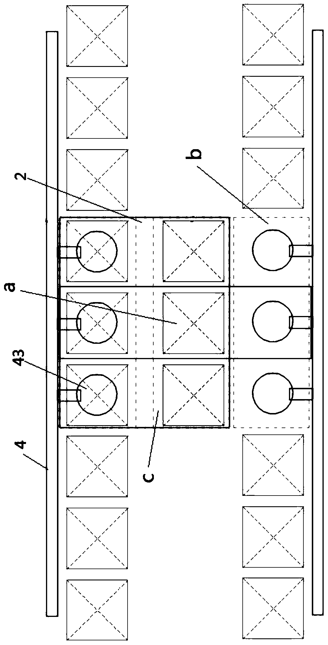
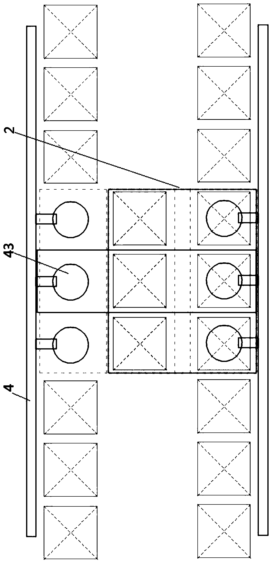
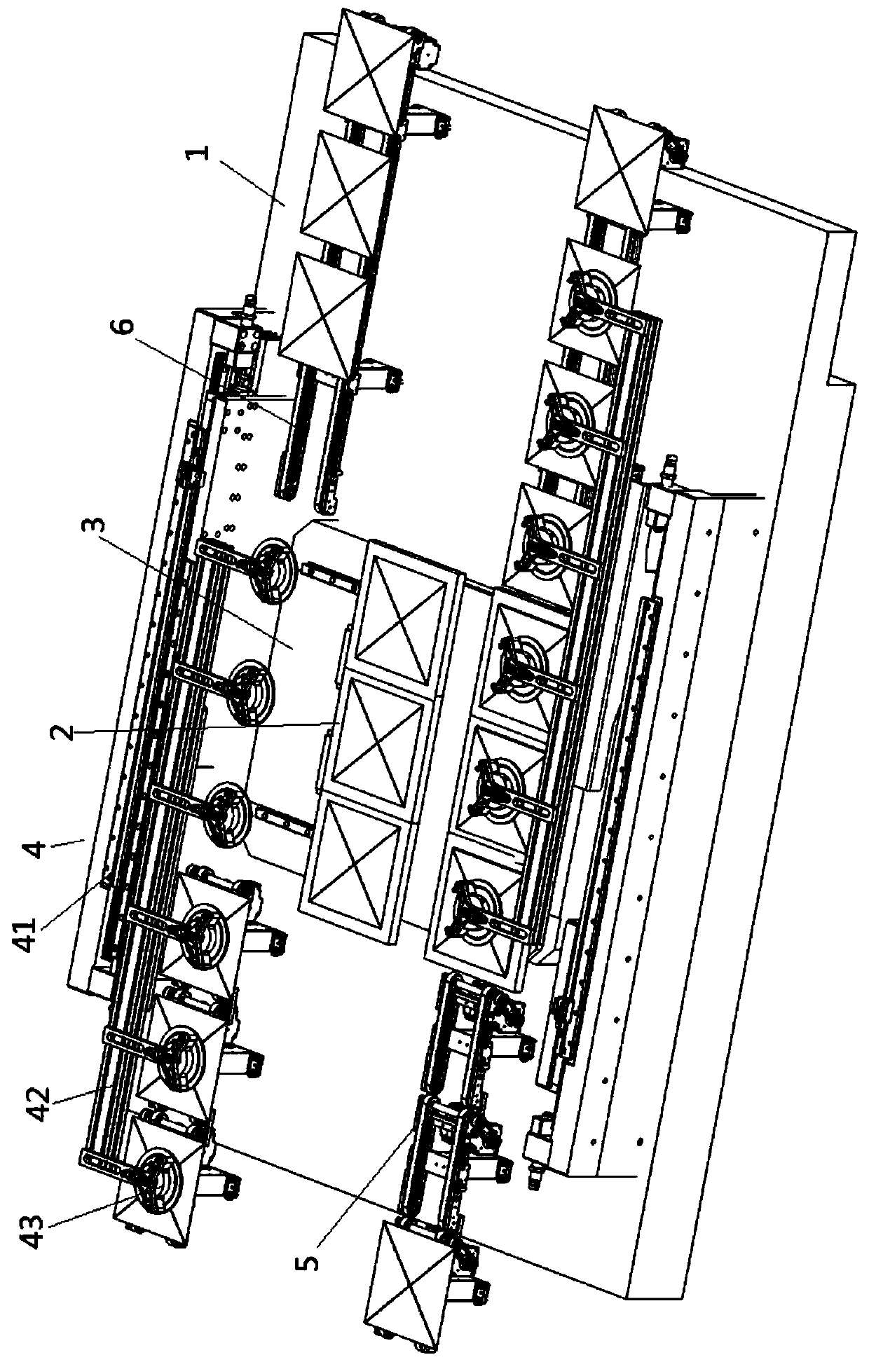
[0038] Embodiment one: if figure 1 , 2 , 3, and 4, the material transmission system of this embodiment includes a workbench 1, an object stage 2, a drive transmission assembly 3 and a loading and unloading mechanism; the above-mentioned object stage 2 is arranged on the upper end of the workbench 1, and is installed on The drive transmission assembly 3 on the workbench 1 is connected by transmission, and the above-mentioned object stage 2 is provided with two groups of discharge positions arranged side by side (a in the figure is the discharge position); the left and right sides above the above-mentioned workbench 1 are respectively Set a group of loading positions (place b in the figure is the material level), set a group of processing positions in the middle (place c in the figure is the processing position), and the above-mentioned drive transmission assembly 3 drives the above-mentioned carrier table 2 to reciprocate left and right, Drive the two sets of discharge positio...

Embodiment 2

[0059] Embodiment two: a kind of material transmission system, see Figure 5 , similar to Embodiment 1, the difference is that the loading and unloading mechanism is a loading and unloading belt conveyor 7 arranged before and after the discharge position, which can be one or a plurality of belt conveyors continuously arranged in the front and rear directions. Now, the discharge position of stage 2 is also arranged on the discharge belt conveyor 8 placed on stage 2, which can be one or a plurality of belt conveyors ( The conveying surfaces are flush with each other), on which one or more materials can be carried, corresponding to one or more discharge positions.

[0060] When used as a processing device for sheet materials, such as in the solar cell industry, the discharge belt conveyor 8 is a negative pressure adsorption belt conveyor.

[0061] At this time, the loading and unloading of materials can be transferred to the discharge position by means of belt conveyor transport...

Embodiment 3

[0063] Embodiment 3: A laser processing equipment, including a laser processing module and the material transmission system in Embodiment 1 or Embodiment 2. The above-mentioned laser processing module is installed on the above-mentioned workbench 1, and its laser scanning head is placed on the above-mentioned Above the processing position, the above-mentioned laser scanning head is used to send out the laser beam downward, and scan and process the materials at a group of the above-mentioned discharge positions that move to the above-mentioned processing position. This laser processing equipment can greatly increase the production capacity , and the laser scanning head is generally used for the scanning processing of the cells to be processed on the two discharge positions, and the layout and design are very reasonable.

[0064] As a preferred solution, there is one laser processing module or a plurality of the same amount as the material processing position, and the materials o...


PUM


Abstract

The invention discloses a material conveying system and laser processing equipment. The material conveying system comprises a workbench, an objective table, a driving transmission assembly and a feeding and discharging mechanism; the objective table is arranged at the upper end of the workbench and is in transmission connection with the driving transmission assembly arranged on the workbench, andtwo sets of discharging stations which are distributed in parallel are arranged on the objective table; a set of feeding stations is arranged on each of the left side and the right side of the upper portion of the workbench, a set of processing stations is arranged in the middle of the workbench, the driving transmission assembly drives the objective table to move left and right in a reciprocatingmode, the two sets of discharging stations are driven to move in a reciprocating mode between the feeding stations on one side and the processing stations, and when one set of discharging stations islocated at the processing stations, the other set of discharging stations is located at the feeding stations on the side corresponding to the discharging stations; and the two feeding and dischargingmechanisms correspond to the two sets of feeding stations correspondingly, and the feeding and discharging mechanisms are used for feeding materials to the feeding positions and transferring the materials on the feeding positions. The system and the equipment have the advantages that the productivity can be improved, and meanwhile, the bottleneck problem that the production is limited due to thefact that the process of the subsequent stage is balanced is effectively solved.

Description

technical field [0001] The invention belongs to the technical field of laser processing, in particular to a material transmission system and laser processing equipment. Background technique [0002] At present, in the production of solar cells, as the size of the product increases, the laser process time becomes longer, and at the same time, the physical capacity of the online equipment in the later process is further improved. The dual-laser equipment in the existing market has encountered capacity bottlenecks. In these online production occasions where the process time increases, it cannot meet the needs of matching the capacity of the front and rear stages. It is easy to think of increasing the production capacity of a single machine by increasing the number of lasers and the number of the same stations, and adopting a structure similar to the high-speed multi-station turntable commonly used in the existing industry. However, if three sets (or multiple sets) of lasers ar...

Claims


Application Information

Patent Timeline
Patent Type & Authority Applications(China)
IPC IPC(8): B23K26/70B65G49/07
CPCB23K26/702B65G49/07
Inventor 徐贵阳胡英
Owner WUHAN DR LASER TECH CORP LTD
Why Eureka
Try Eureka